 for instructions on how to create new materials. Next go to an elevation, section or 3D view so you can see the wall you wish to change. Once you’re in the view select the Split Face tool on the lower tool bar. You cursor now has a razor knife next to it. You must select the wall in which you intend to split. Once you’ve selected it you are in sketch mode. Now you can sketch a line wherever you want the new material to go. Remember it has to be a closed loop, no intersecting lines. Finish the sketch. Now select the Paint Bucket on the lower tool bar next to the Split Face tool. On the Type Selector choose the material created for the area you wish to change. Hover the Paint Bucket over one of the sketched lines and left click to add the material. The sketched area changes to the designated material.
Note: This is not view specific, so it will be visible in all views.
for instructions on how to create new materials. Next go to an elevation, section or 3D view so you can see the wall you wish to change. Once you’re in the view select the Split Face tool on the lower tool bar. You cursor now has a razor knife next to it. You must select the wall in which you intend to split. Once you’ve selected it you are in sketch mode. Now you can sketch a line wherever you want the new material to go. Remember it has to be a closed loop, no intersecting lines. Finish the sketch. Now select the Paint Bucket on the lower tool bar next to the Split Face tool. On the Type Selector choose the material created for the area you wish to change. Hover the Paint Bucket over one of the sketched lines and left click to add the material. The sketched area changes to the designated material.
Note: This is not view specific, so it will be visible in all views.
Wednesday, July 30, 2008
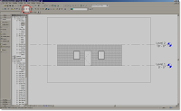
Split Face Tool
The Split Face tool is a tool everyone should understand. Its function is to allow you to select the face of an element and change its material with the paint bucket.
Here’s how it works:
Let’s say you have a wall that has a particular material assigned to it. This particular wall is being used in a restroom where part of it will be ceramic tile and part of it will remain the original material but the tile doesn’t always maintain the same elevation. To accomplish this you would have to use two different walls of the same wall type. Wall type A with the tile at X height, and wall type B with the tile at Y height. This may result in confusion and difficulty in keeping the walls together. The Split Face tool allows you to accomplish this much faster and easier.
First of all if you don’t have the material for the wall, you need to create one. Click here for instructions on how to create new materials. Next go to an elevation, section or 3D view so you can see the wall you wish to change. Once you’re in the view select the Split Face tool on the lower tool bar. You cursor now has a razor knife next to it. You must select the wall in which you intend to split. Once you’ve selected it you are in sketch mode. Now you can sketch a line wherever you want the new material to go. Remember it has to be a closed loop, no intersecting lines. Finish the sketch. Now select the Paint Bucket on the lower tool bar next to the Split Face tool. On the Type Selector choose the material created for the area you wish to change. Hover the Paint Bucket over one of the sketched lines and left click to add the material. The sketched area changes to the designated material.
Note: This is not view specific, so it will be visible in all views.
for instructions on how to create new materials. Next go to an elevation, section or 3D view so you can see the wall you wish to change. Once you’re in the view select the Split Face tool on the lower tool bar. You cursor now has a razor knife next to it. You must select the wall in which you intend to split. Once you’ve selected it you are in sketch mode. Now you can sketch a line wherever you want the new material to go. Remember it has to be a closed loop, no intersecting lines. Finish the sketch. Now select the Paint Bucket on the lower tool bar next to the Split Face tool. On the Type Selector choose the material created for the area you wish to change. Hover the Paint Bucket over one of the sketched lines and left click to add the material. The sketched area changes to the designated material.
Note: This is not view specific, so it will be visible in all views.
Monday, July 28, 2008
The Magic of Plan Regions
Ever run across a situation where you need to see something in plan but it sits above the current view range? Oh, you’re not sure what the view range is or how it works? Here’s how they work.
Every plan and RCP view has a view property called View Range, also known as a visible range. The view range is a set of horizontal planes that control object visibility and display in the view. The horizontal planes are Top Clip Plane, Cut Plane, Bottom Clip Plane, and View Depth.
As their names imply, the top and bottom clip plane represent the topmost and bottommost portion of the view range. The cut plane is a plane that determines at what height certain elements in the view are shown cut. These 3 planes define the primary range of the view range.
View Depth is an additional plane outside of the primary range. You can set the level of view depth to show elements below the Bottom Clip Plane. By default, it is coincident with the Bottom Clip Plane. You can set it to levels below the Bottom Clip Plane.
Elements outside the visible range of the view do not display in the view. The exception to this is if you set the view underlay to a level outside the visible range.
Now that you understand view range, I’m going to show you how to override it. As stated above, there are times when you have elements in your plan that live above the existing view range, such as a clerestory window for example. In these instances you can use a Plan Region to override the existing view range. Here’s how you do it: 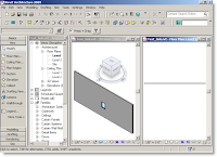 In the plan, where you want to see the element, go to the view tab on the design bar. Select the Plan Region tool. While in sketch mode, draw a rectangle around the element you wish to see. Before finishing the sketch, set the Region Properties so you’ll be able to see the element in the current view. The Plan Region is set up exactly like the View Range in that there are 3 planes. Set them up just like you’re
 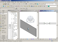 setting the View Range, only higher or lower depending on where the element is. Once the properties are set, click Finish Sketch, you’re done. You should be able to see the element in the plan now. If not, select the Plan Region and adjust the view range until you see the element.
Click here to view the video tutorial.
setting the View Range, only higher or lower depending on where the element is. Once the properties are set, click Finish Sketch, you’re done. You should be able to see the element in the plan now. If not, select the Plan Region and adjust the view range until you see the element.
Click here to view the video tutorial.
 In the plan, where you want to see the element, go to the view tab on the design bar. Select the Plan Region tool. While in sketch mode, draw a rectangle around the element you wish to see. Before finishing the sketch, set the Region Properties so you’ll be able to see the element in the current view. The Plan Region is set up exactly like the View Range in that there are 3 planes. Set them up just like you’re
  setting the View Range, only higher or lower depending on where the element is. Once the properties are set, click Finish Sketch, you’re done. You should be able to see the element in the plan now. If not, select the Plan Region and adjust the view range until you see the element.
Click here to view the video tutorial.
setting the View Range, only higher or lower depending on where the element is. Once the properties are set, click Finish Sketch, you’re done. You should be able to see the element in the plan now. If not, select the Plan Region and adjust the view range until you see the element.
Click here to view the video tutorial.
Tuesday, July 22, 2008
Double click level to access views
Did you know that you can access plan view from elevation and section views the same way you access section and elevation views, by double clicking on the callout heads?
Go to an elevation or section view and double click on the level head you wish to go to. Viola you’re there. Cool huh. It's the little things.
Thursday, July 17, 2008
Reference Lines (reference planes long lost brother)
Yes it's true, reference planes have a long lost brother, they were separated a birth or something like that. Anyway like brothers, Reference Lines and Reference Planes have there differences. This post will cover Reference Lines and why you should be using them.
Reference Lines in my opinion are mostly overlooked. I must admit I'm guilty of it myself. However, as this post will show, Reference Lines are quite useful for some very specific functions.
You can only access Reference Lines in a family creating mode, that means only when creating a component family in the Family Editor or an in-place family in your project. Reference Lines define two perpendicular work planes, and you can manage the orientation of a reference line parametrically with the Angle parameter. You use the TAB key to select a work plane in which you want to work.
Click here to view video tutorial.
Wednesday, July 16, 2008
Linking Revit Views
So it's been quite a while since my last post, but a guy has to vacation once in a while to keep his sanity...right? Anyway today's post will cover how you can link a particular view from a Revit link.
Often we're faced with the challenge of managing buildings or multiple buildings in one project file. All too often I see users trying to add too much to one project file and end up with a file size of 100+ MB. Now lets be clear, it's not so much the file size as it is the performance of the file. You can have file sizes upwards of 200MB and the performance is still manageable. In contrast to that I've seen files of less than 100MB and the performance is so slow no one can get anything done. To alleviate some of this I suggest to split up your project into logical pieces. For example, if I have a project in which more than one building is being designed, I'll most likely separate these buildings and place them in their own file. After which I'll link them back into what I call a "host file". This file usually contains the site component of the project. What this allows you to do is move, rotate, or otherwise place the building wherever you want without having to reorient your model for documentation.
This leads me to the purpose of my post today. Since you've placed the models in one file, why not go ahead and create all the sheets in the same model. The problem is you don't have any of the views set up in the host file to plot from, but it takes only a couple of quick clicks to have all the views created in each model file linked in to the host file ready to place on sheets.
Here's what you do:  Once you've linked and placed you models in the host file, go to the view you want to document. Type in VG to get to the Visibility Graphics of that view. The Visibility / Graphics Overrides dialog opens. You'll notice a new tab labeled Revit Links, click to open it. You should see the Revit links you've linked into the project. Under the Display Settings column you'll notice it is set to By Host View. This means whatever you've set your VG to for this view, the link will display the sa
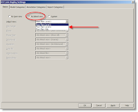 me settings. This is what we want to change. Click the By Host View button, the RVT Link Display Settings opens. Choose By Linked View instead of By Host View. The Linked View category becomes active. You may now choose from the drop down menu which view you want to see. Once you've chosen the view, you can drag it to the appropriate sheet.
One side note: The 2008 and earlier versions of Revit will only allow you to link plan views. The 2009 version will allow you to link plans as well as elevations, sections, and sections. Pretty cool huh?
me settings. This is what we want to change. Click the By Host View button, the RVT Link Display Settings opens. Choose By Linked View instead of By Host View. The Linked View category becomes active. You may now choose from the drop down menu which view you want to see. Once you've chosen the view, you can drag it to the appropriate sheet.
One side note: The 2008 and earlier versions of Revit will only allow you to link plan views. The 2009 version will allow you to link plans as well as elevations, sections, and sections. Pretty cool huh?
 Once you've linked and placed you models in the host file, go to the view you want to document. Type in VG to get to the Visibility Graphics of that view. The Visibility / Graphics Overrides dialog opens. You'll notice a new tab labeled Revit Links, click to open it. You should see the Revit links you've linked into the project. Under the Display Settings column you'll notice it is set to By Host View. This means whatever you've set your VG to for this view, the link will display the sa
 me settings. This is what we want to change. Click the By Host View button, the RVT Link Display Settings opens. Choose By Linked View instead of By Host View. The Linked View category becomes active. You may now choose from the drop down menu which view you want to see. Once you've chosen the view, you can drag it to the appropriate sheet.
One side note: The 2008 and earlier versions of Revit will only allow you to link plan views. The 2009 version will allow you to link plans as well as elevations, sections, and sections. Pretty cool huh?
me settings. This is what we want to change. Click the By Host View button, the RVT Link Display Settings opens. Choose By Linked View instead of By Host View. The Linked View category becomes active. You may now choose from the drop down menu which view you want to see. Once you've chosen the view, you can drag it to the appropriate sheet.
One side note: The 2008 and earlier versions of Revit will only allow you to link plan views. The 2009 version will allow you to link plans as well as elevations, sections, and sections. Pretty cool huh?
Wednesday, July 2, 2008
Adding new Drafting and Model patterns
Ever find yourself looking for more fill patterns than what you find already in Revit? Well, I can tell you plenty of people do. In fact I was asked just today if I could create one that didn't already exist. It's not really that difficult to create a simply pattern. If you want a more complicated fill pattern such as sand, or concrete you'll have to create a pattern file in notepad following some specific rules. For this post I'll cover the easy method and save the difficult method for a Revit lunch and learn.
Before we go any further we should discuss the difference between Drafting and Model Patterns. Drafting patterns typically show up when you are cutting a section through a component. For example, a wall is made up of specific layers of materials. When cutting a section through the wall you will find a specific pattern for each material. These patterns are Drafting Fill Patterns. Drafting Fill Patterns act much like a hatch patterns in AutoCAD. Model Fill Patterns are a little more sophisticated than DFP. They are typically used as surface patterns on walls, roofs, or ceilings. The reason you would use a MFP on the surface of these components is because you can select them independently of the component. For example, I have a wall with a 8x8x16 MFP as its surface pattern. I have the ability to align the pattern with the edge of the wall so I don't get an odd condition there. Openings in the wall now appear in the right place avoiding odd conditions as well. OK, on with the post.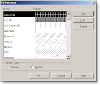 Open Revit and click Settings → Fill Patterns... the Fill Patterns dialog opens. Choose what type of pattern you are going to create and select New. Selecting New will take you to the New Pattern dialog. Here we should discuss the Orientation in Host Layers. You can control the orientation of the pattern, but only in Host Layers, meaning the layer of a wall, floor or roof. It DOES NOT work on a filled region.
Orient To View: Selecting this option will orient the pattern to the view you are in regardless of angle or placement of its host.
Keep Readable: Revit will determine the best orientation for the fill
Open Revit and click Settings → Fill Patterns... the Fill Patterns dialog opens. Choose what type of pattern you are going to create and select New. Selecting New will take you to the New Pattern dialog. Here we should discuss the Orientation in Host Layers. You can control the orientation of the pattern, but only in Host Layers, meaning the layer of a wall, floor or roof. It DOES NOT work on a filled region.
Orient To View: Selecting this option will orient the pattern to the view you are in regardless of angle or placement of its host.
Keep Readable: Revit will determine the best orientation for the fill 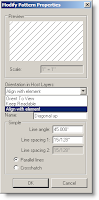 patter for the best possible result.
Align with Element: Revit essentially freezes the pattern inside the host, so no matter what you do the patter will always keep the same angle.
Line Angle: I hope this is self explanatory.
Line Spacing: Remember the scale is 1"=1" and this can't be changed for a simple pattern.
Line Spacing 2: You need this only if you choose Crosshatch instead of Parallel lines. You can have two different line spacings.
Once you have your setting selected you can click OK and you're done.
patter for the best possible result.
Align with Element: Revit essentially freezes the pattern inside the host, so no matter what you do the patter will always keep the same angle.
Line Angle: I hope this is self explanatory.
Line Spacing: Remember the scale is 1"=1" and this can't be changed for a simple pattern.
Line Spacing 2: You need this only if you choose Crosshatch instead of Parallel lines. You can have two different line spacings.
Once you have your setting selected you can click OK and you're done.
 Open Revit and click Settings → Fill Patterns... the Fill Patterns dialog opens. Choose what type of pattern you are going to create and select New. Selecting New will take you to the New Pattern dialog. Here we should discuss the Orientation in Host Layers. You can control the orientation of the pattern, but only in Host Layers, meaning the layer of a wall, floor or roof. It DOES NOT work on a filled region.
Orient To View: Selecting this option will orient the pattern to the view you are in regardless of angle or placement of its host.
Keep Readable: Revit will determine the best orientation for the fill
Open Revit and click Settings → Fill Patterns... the Fill Patterns dialog opens. Choose what type of pattern you are going to create and select New. Selecting New will take you to the New Pattern dialog. Here we should discuss the Orientation in Host Layers. You can control the orientation of the pattern, but only in Host Layers, meaning the layer of a wall, floor or roof. It DOES NOT work on a filled region.
Orient To View: Selecting this option will orient the pattern to the view you are in regardless of angle or placement of its host.
Keep Readable: Revit will determine the best orientation for the fill 
 patter for the best possible result.
Align with Element: Revit essentially freezes the pattern inside the host, so no matter what you do the patter will always keep the same angle.
Line Angle: I hope this is self explanatory.
Line Spacing: Remember the scale is 1"=1" and this can't be changed for a simple pattern.
Line Spacing 2: You need this only if you choose Crosshatch instead of Parallel lines. You can have two different line spacings.
Once you have your setting selected you can click OK and you're done.
patter for the best possible result.
Align with Element: Revit essentially freezes the pattern inside the host, so no matter what you do the patter will always keep the same angle.
Line Angle: I hope this is self explanatory.
Line Spacing: Remember the scale is 1"=1" and this can't be changed for a simple pattern.
Line Spacing 2: You need this only if you choose Crosshatch instead of Parallel lines. You can have two different line spacings.
Once you have your setting selected you can click OK and you're done.
Tuesday, July 1, 2008
Importing Sketch Up Models (updated)
As is the case, I sometimes run across information that adds to or even supersedes information I have previously written about. This is one of those times. I ran across some information regarding importing Sketch Up models into Revit. Turns out you don't need to go through the Family Editor to import Sketch Up data to be able to use it.
Here are the amended steps:
Instead of opening up the Family Editor, all you have to do is click the Create Mass tool under the Massing tab on the Design Bar. Once you have named the mass you will be in sketch mode. Then and only then can you import the Sketch Up file into Revit. Follow all the same steps to import found in Importing Sketch Up Models. Using this method still gives you all the functionality as if it were a Component family, but it is in actuality an In-Place family. Which, in this case, doesn't really matter because you're not really going to need to save it to a file to be used in another project.
Click here for video tutorial on SmithGroup network.
Subscribe to:
Posts (Atom)