Showing posts with label Import. Show all posts
Showing posts with label Import. Show all posts
Tuesday, July 1, 2008
Importing Sketch Up Models (updated)
As is the case, I sometimes run across information that adds to or even supersedes information I have previously written about. This is one of those times. I ran across some information regarding importing Sketch Up models into Revit. Turns out you don't need to go through the Family Editor to import Sketch Up data to be able to use it.
Here are the amended steps:
Instead of opening up the Family Editor, all you have to do is click the Create Mass tool under the Massing tab on the Design Bar. Once you have named the mass you will be in sketch mode. Then and only then can you import the Sketch Up file into Revit. Follow all the same steps to import found in Importing Sketch Up Models. Using this method still gives you all the functionality as if it were a Component family, but it is in actuality an In-Place family. Which, in this case, doesn't really matter because you're not really going to need to save it to a file to be used in another project.
Click here for video tutorial on SmithGroup network.
Thursday, June 26, 2008
Importing Sketch Up Models
As I've mentioned in previous post, using other applications such as Sketch Up in schematic design is perfectly acceptable in my book. The option to import that data into Revit and use it is a good option for anyone in the schematic phase of a project.
This post will explore the methods of importing 3D geometry from Sketch Up and using that data to build you Revit model.
As usual I will add some images as well as a video tutorial to aid in the learning process. One of these days I might even add audio to the videos.
Importing Sketch Up 3D Data
First of all you have to know how to create something in Sketch Up in order to import said data into Revit. Since this is a Revit blog, I won't be going into how to accomplish this.
The steps to importing a SU file aren't too different from importing a dwg file. The difference is you don't want to import the SU data directly into your project. You want to import the data into a Revit Family. Let me explain. In order to utilize some of the Massing tools in Revit with the SU geometry, you must import it into a Revit Family. These tools include Wall by Face, Curtain System, Roof by Face, and Floor by Face. If the SU geometry is imported directly into the project you will not be able to select the face of the object. Being able to select the face of an object is essential to creating a Wall by Face, Roof by Face...etc.
Open a new session of Revit, click File on the File Menu bar. Choose New - Family.
This will take you to the New Family dialog box. Choose Mass from the list of templates.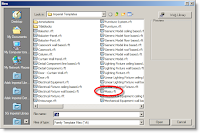 The Family Editor opens. The Family Editor will have the same interface as a regular project will. The difference is you don't have as many tools in the Design Bar. You have only the tools needed to create a family.
Once you're in the Family Editor you'll notice two Reference Planes. Where these two planes meet is the center of the family, as well as the insertion point when placing it into the project. Import the SU geometry the same way you would import a dwg in the project.
The Family Editor opens. The Family Editor will have the same interface as a regular project will. The difference is you don't have as many tools in the Design Bar. You have only the tools needed to create a family.
Once you're in the Family Editor you'll notice two Reference Planes. Where these two planes meet is the center of the family, as well as the insertion point when placing it into the project. Import the SU geometry the same way you would import a dwg in the project. 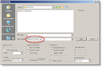 Select File → Import/Link → CAD Formats browse to find the file. Make sure you have selected Sketch up files as the Files of Type. The other setting should be set as indicated in the image.
Once you have the settings set click open. The SU geometry is imported into the project. Depending on how large the geometry is you may have to zoom out to see it all.
Save and name the family logically so you can find it when you load it into your project. I suggest adding the word Mass to the name you give your family.
After saving and naming the family, select the Load into Project button on the Design Bar. This will add the family to your project. If you don't currently have a project open this would be a good time to do that.
In your project open the Massing tool on the Design Bar. If you don't see it in the Design Bar you have to right click in an empty space on the Design Bar and choose it from the list). Select the Place Mass button, this should automatically select the new massing family you just loaded into the project from the Type Selector.
After clicking the Place Mass button move you mouse into the View Window to place the mass. Notice you get the universal sign for NOT GOING TO HAPPEN appears...frustration
Select File → Import/Link → CAD Formats browse to find the file. Make sure you have selected Sketch up files as the Files of Type. The other setting should be set as indicated in the image.
Once you have the settings set click open. The SU geometry is imported into the project. Depending on how large the geometry is you may have to zoom out to see it all.
Save and name the family logically so you can find it when you load it into your project. I suggest adding the word Mass to the name you give your family.
After saving and naming the family, select the Load into Project button on the Design Bar. This will add the family to your project. If you don't currently have a project open this would be a good time to do that.
In your project open the Massing tool on the Design Bar. If you don't see it in the Design Bar you have to right click in an empty space on the Design Bar and choose it from the list). Select the Place Mass button, this should automatically select the new massing family you just loaded into the project from the Type Selector.
After clicking the Place Mass button move you mouse into the View Window to place the mass. Notice you get the universal sign for NOT GOING TO HAPPEN appears...frustration 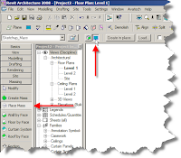 starts to build. No need to worry all you need to do is select the Place on Work Plane button located on the Options Bar next to the Type Selector. By default the Place on Face button is selected, don't ask me why.
Once you have placed your SU geometry you may need to zoom out to view it. Open up a 3D view and check out you handy work. Don't get too comfortable though, your not done yet. Just having some massing in your project that represents a model is not enough. This is just a DUMB piece of geometry. You can't add doors or windows to it, your can't even get basic information from it. What good is it you ask? Well, not much...but because we took the time to place the SU geometry in a family we will be able to create walls, floors and roofs from the existing faces.
Open up a 3D view so you can see the entire SU geometry. Go to the Massing tab on the Design Bar and choose Wall by Face. Select the wall type you want from the Type Selector. (Pay attention to the setting on the Options Bar). Place your mouse over the edge of the face you want to add a wall to and left click, the wall will take the exact shape of the face of the mass you selected.
Curtain Systems, Floors by Face and Roof by Face are a little different. The difference is that when you are done selecting the face of the mass, you'll have to click the Create System button on the Options Bar to finish the command.
Now you know, I hope you'll try it. This method is a good one, but you'll discover some things aren't so great. For instance, what if the massing model changes in SU? Now what? Well...you have to create a new massing family based on the new information and reinsert it into the project.
If you learn the massing tools in Revit THIS WON'T HAPPEN. I'll discuss this method next time. Meanwhile check out this video tutorial.
Click here to view it from the SmithGroup network.
starts to build. No need to worry all you need to do is select the Place on Work Plane button located on the Options Bar next to the Type Selector. By default the Place on Face button is selected, don't ask me why.
Once you have placed your SU geometry you may need to zoom out to view it. Open up a 3D view and check out you handy work. Don't get too comfortable though, your not done yet. Just having some massing in your project that represents a model is not enough. This is just a DUMB piece of geometry. You can't add doors or windows to it, your can't even get basic information from it. What good is it you ask? Well, not much...but because we took the time to place the SU geometry in a family we will be able to create walls, floors and roofs from the existing faces.
Open up a 3D view so you can see the entire SU geometry. Go to the Massing tab on the Design Bar and choose Wall by Face. Select the wall type you want from the Type Selector. (Pay attention to the setting on the Options Bar). Place your mouse over the edge of the face you want to add a wall to and left click, the wall will take the exact shape of the face of the mass you selected.
Curtain Systems, Floors by Face and Roof by Face are a little different. The difference is that when you are done selecting the face of the mass, you'll have to click the Create System button on the Options Bar to finish the command.
Now you know, I hope you'll try it. This method is a good one, but you'll discover some things aren't so great. For instance, what if the massing model changes in SU? Now what? Well...you have to create a new massing family based on the new information and reinsert it into the project.
If you learn the massing tools in Revit THIS WON'T HAPPEN. I'll discuss this method next time. Meanwhile check out this video tutorial.
Click here to view it from the SmithGroup network.
 The Family Editor opens. The Family Editor will have the same interface as a regular project will. The difference is you don't have as many tools in the Design Bar. You have only the tools needed to create a family.
Once you're in the Family Editor you'll notice two Reference Planes. Where these two planes meet is the center of the family, as well as the insertion point when placing it into the project. Import the SU geometry the same way you would import a dwg in the project.
The Family Editor opens. The Family Editor will have the same interface as a regular project will. The difference is you don't have as many tools in the Design Bar. You have only the tools needed to create a family.
Once you're in the Family Editor you'll notice two Reference Planes. Where these two planes meet is the center of the family, as well as the insertion point when placing it into the project. Import the SU geometry the same way you would import a dwg in the project.  Select File → Import/Link → CAD Formats browse to find the file. Make sure you have selected Sketch up files as the Files of Type. The other setting should be set as indicated in the image.
Once you have the settings set click open. The SU geometry is imported into the project. Depending on how large the geometry is you may have to zoom out to see it all.
Save and name the family logically so you can find it when you load it into your project. I suggest adding the word Mass to the name you give your family.
After saving and naming the family, select the Load into Project button on the Design Bar. This will add the family to your project. If you don't currently have a project open this would be a good time to do that.
In your project open the Massing tool on the Design Bar. If you don't see it in the Design Bar you have to right click in an empty space on the Design Bar and choose it from the list). Select the Place Mass button, this should automatically select the new massing family you just loaded into the project from the Type Selector.
After clicking the Place Mass button move you mouse into the View Window to place the mass. Notice you get the universal sign for NOT GOING TO HAPPEN appears...frustration
Select File → Import/Link → CAD Formats browse to find the file. Make sure you have selected Sketch up files as the Files of Type. The other setting should be set as indicated in the image.
Once you have the settings set click open. The SU geometry is imported into the project. Depending on how large the geometry is you may have to zoom out to see it all.
Save and name the family logically so you can find it when you load it into your project. I suggest adding the word Mass to the name you give your family.
After saving and naming the family, select the Load into Project button on the Design Bar. This will add the family to your project. If you don't currently have a project open this would be a good time to do that.
In your project open the Massing tool on the Design Bar. If you don't see it in the Design Bar you have to right click in an empty space on the Design Bar and choose it from the list). Select the Place Mass button, this should automatically select the new massing family you just loaded into the project from the Type Selector.
After clicking the Place Mass button move you mouse into the View Window to place the mass. Notice you get the universal sign for NOT GOING TO HAPPEN appears...frustration  starts to build. No need to worry all you need to do is select the Place on Work Plane button located on the Options Bar next to the Type Selector. By default the Place on Face button is selected, don't ask me why.
Once you have placed your SU geometry you may need to zoom out to view it. Open up a 3D view and check out you handy work. Don't get too comfortable though, your not done yet. Just having some massing in your project that represents a model is not enough. This is just a DUMB piece of geometry. You can't add doors or windows to it, your can't even get basic information from it. What good is it you ask? Well, not much...but because we took the time to place the SU geometry in a family we will be able to create walls, floors and roofs from the existing faces.
Open up a 3D view so you can see the entire SU geometry. Go to the Massing tab on the Design Bar and choose Wall by Face. Select the wall type you want from the Type Selector. (Pay attention to the setting on the Options Bar). Place your mouse over the edge of the face you want to add a wall to and left click, the wall will take the exact shape of the face of the mass you selected.
Curtain Systems, Floors by Face and Roof by Face are a little different. The difference is that when you are done selecting the face of the mass, you'll have to click the Create System button on the Options Bar to finish the command.
Now you know, I hope you'll try it. This method is a good one, but you'll discover some things aren't so great. For instance, what if the massing model changes in SU? Now what? Well...you have to create a new massing family based on the new information and reinsert it into the project.
If you learn the massing tools in Revit THIS WON'T HAPPEN. I'll discuss this method next time. Meanwhile check out this video tutorial.
Click here to view it from the SmithGroup network.
starts to build. No need to worry all you need to do is select the Place on Work Plane button located on the Options Bar next to the Type Selector. By default the Place on Face button is selected, don't ask me why.
Once you have placed your SU geometry you may need to zoom out to view it. Open up a 3D view and check out you handy work. Don't get too comfortable though, your not done yet. Just having some massing in your project that represents a model is not enough. This is just a DUMB piece of geometry. You can't add doors or windows to it, your can't even get basic information from it. What good is it you ask? Well, not much...but because we took the time to place the SU geometry in a family we will be able to create walls, floors and roofs from the existing faces.
Open up a 3D view so you can see the entire SU geometry. Go to the Massing tab on the Design Bar and choose Wall by Face. Select the wall type you want from the Type Selector. (Pay attention to the setting on the Options Bar). Place your mouse over the edge of the face you want to add a wall to and left click, the wall will take the exact shape of the face of the mass you selected.
Curtain Systems, Floors by Face and Roof by Face are a little different. The difference is that when you are done selecting the face of the mass, you'll have to click the Create System button on the Options Bar to finish the command.
Now you know, I hope you'll try it. This method is a good one, but you'll discover some things aren't so great. For instance, what if the massing model changes in SU? Now what? Well...you have to create a new massing family based on the new information and reinsert it into the project.
If you learn the massing tools in Revit THIS WON'T HAPPEN. I'll discuss this method next time. Meanwhile check out this video tutorial.
Click here to view it from the SmithGroup network.
Monday, June 16, 2008
In the Beginning
It has been difficult for me to choose the very first topic for the new blog, so I thought I'd start at the beginning. For most of you, starting a Revit project will be something of a new experience. For this reason I have decided to demonstrate how to begin a project.
It's common in this office to use applications other than Revit to begin a project. I say if you feel more comfortable using something other than Revit, then more power to you. The nice thing about Revit is you can use that data to begin your Revit model.
This post will explore how to use data created in other applications to begin your Revit model, specifically AutoCAD and Sketch Up.
Importing Data: Revit will import the following file types: DWG (AutoCAD) DGN (Microstation) SKP (Sketch Up) SAT (ACIS 3D Model File)
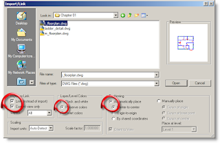
Import Settings (DWG) Once you have sufficient data to use, open Revit to begin a new project. You shouldn't have to worry about things such as line types, text styles, or families, because they are apart of the project template. We'll discuss the project template in a different post. Choose these setting when importing dwg data to use as a background:

Link instead of import because you never know when the dwg might change, and it doesn't take up as much memory as does straight importing. It should be pointed out that even though linking a dwg is better than importing, you should always be aware that the more dwg's imported into the project the slower it will run. To avoid this you should delete files no longer necessary to the project. Current view only to take advantage of the option on the option bar allowing you to toggle between foreground and background. Preserve colors so you will be able to tell the difference between your model and the dwg lines. Automatically place Center-to-center Revit will search for the center of the dwg and place it into the center of your Revit project. It is possible to acquire the coordinates of the dwg. Typically the civil engineer will use these coordinates to begin their drawing in AutoCAD. We will discuss how to do this in an upcoming post.
Adding Walls Start by making sure the settings for your wall are correct. Do this by checking the Options Bar at the top of the View Window. After choosing the wall, you'll need to decide how you want to go about building your walls. On the Options Bar you can choose to either pick the lines in the DWG or draw the lines over the top of the DWG. Either way you must pay close attention to how the wall is being drawn. When you begin to draw you'll get a green dashed line showing where the Location Line is. This should help you determine how the wall is going to look once created. This video tutorial should help: Click here if you're on the SmithGroup network. Click here if you're not on the network.
Subscribe to:
Posts (Atom)