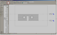
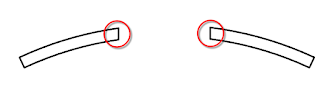
When creating an opening in a curved wall, the Opening – Wall Opening tool cuts an opening that is perpendicular to the radius of the curved wall.
 This post will discuss how to create and opening in a curved wall when you want the sides of the opening to be parallel.
 In – Place Void Family
Select the CREATE button under the Modeling tab on the Design Bar.
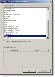
Choose Walls for the Family Category and Parameters so the void works with the V.G.
In – Place Void Family
Select the CREATE button under the Modeling tab on the Design Bar.
Choose Walls for the Family Category and Parameters so the void works with the V.G.
Name the in – place family logically.
Once you click OK, you will be in sketch mode where you will build the Void.

Make sure the settings on the Options Bar are set so the void creates the correct size of opening. The length and width of the opening only need to be big enough to cut the wall completely.
 Cut Geometry
After sketching the void shape you can click Finish Sketch on the Design Bar to complete the void. The orange color of the void indicates the position of the void.
Because the void is an in – place family, it will not automatically cut the object it comes in contact with. For this to occur you have to select the Cut Geometry button on the lower Tool Bar.
Cut Geometry
After sketching the void shape you can click Finish Sketch on the Design Bar to complete the void. The orange color of the void indicates the position of the void.
Because the void is an in – place family, it will not automatically cut the object it comes in contact with. For this to occur you have to select the Cut Geometry button on the lower Tool Bar.
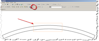 It doesn’t matter which object you choose first to cut the void out of the wall.
After you’ve cut the void out of the wall you can select the Finish Family button on the Design Bar. You should have a section cut out of the wall with the sides parallel to each other. If you don’t get the desired affect, go back and check the height of the void you created. If that looks ok, you might want to check the View Range for the view.
It doesn’t matter which object you choose first to cut the void out of the wall.
After you’ve cut the void out of the wall you can select the Finish Family button on the Design Bar. You should have a section cut out of the wall with the sides parallel to each other. If you don’t get the desired affect, go back and check the height of the void you created. If that looks ok, you might want to check the View Range for the view.
 First open a new family template by clicking File → New → Family and selecting Profile.rft from the list of template files. Once in the Family Editor you’ll notice vertical and horizontal reference planes. Think of the vertical reference plane as the wall surface. The horizontal reference plane will either be the top or bottom of the sweep. In my experience if you draw you profile to the right of the vertical plane the profile will end up on the surface of the wall, not inside the wall. Now all you have to do is draw the profile you want to see on the wall. Remember it has to be a closed loop. This means no intersecting lines or gaps. Once you’ve drawn the profile, save it and load it into your project. In the project, navigate to the Modeling tab on the Design Bar and click the Host Sweep button. Choose the
 profile you’ve just loaded from the Type Selector. Place your cursor over the wall you want to add the profile, and it should appear on the wall. Notice on the Options Bar you can choose horizontal or vertical. Once you’ve placed it you will have to go to the Options Bar and click the Start Next button to continue with the next placement of your profile. This is an easy way to get a pop out or whatever shape you want on your wall without too much trouble.