Hey everyone. Hope you're having a great holiday season. I just wanted to put in a shameless plug for my new course on Pluralsight.
This course is geared toward those who have never opened Revit MEP. I'm really proud of this course and believe it's just what people are looking for. If you or someone you know are looking for a truly fundamentals course with some excellent commentary, then please, check out my course.
Sunday, December 11, 2016
Tuesday, September 6, 2016
I know I put that CAD file in here somewhere
I know it's hard to believe, but we still use CAD files, shocking isn't it? Even though civil, landscape, and other consultants participate in the BIM process, they don't always work in Revit, therefore sometimes we link in dwg's from them. And that's OK. We're still in a transition stage in the industry and may be in this stage for a little while longer. In the meantime there are some nuances when it comes to linking and viewing dwg's in Revit.
Nested vs Direct Link
Of course you know you should always link dwg's instead of importing, but maybe you didn't know it's possible to view nested dwg's. Let me explain. If the architect links a dwg provided by civil, landscape, or even a furniture vendor into the architecture model, and then the architecture model is linked into a different Revit model, you have a nested dwg. Whomever the beneficiary of this linked model now has the ability to view the nested dwg without having to directly link the dwg into their model. Please be aware that if the architect links the dwg to the "Current View Only" option, the "Linked View" in the RVT Link Display Settings dialog will have to be set to that specific view.


The downside to Nested Links
The downside to nested links is you can't control the dwg layers as easily as a direct link. Direct linked dwg's allow you to query the object and either hide or delete layers from the Import Instance Query dialog. In a nested dwg scenario you can still control the layers, but you have to do it through the RVT Link Display Settings> Import Categories tab. In this scenario you can't query the lines so it helps to know the layers that make up the line work in the dwg.

In the end either method works. There are advantages and disadvantages to both. The next time you have to link a dwg into your model, decide as a team how you approach it. This potentially affects all team members regardless of discipline. Discussing this up front on a team level will yield a more consistent work flow which improves your process.
Monday, August 1, 2016
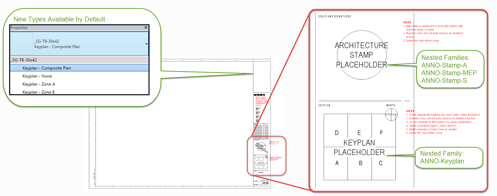
Nested Key Plan and Stamp families... Am I late to the party?
Why didn't I think of this sooner?
Actually why didn't I think of this at all? We just implemented nested stamp and key plan families in our title block families. I wish I could say it was my idea, but as is usually the case one of our power users suggested it.
I love things that make our lives easier
All we did is create place holder annotation families for a stamp and a key plan. Then we nested those place holder families into our standard title block. Now when people want to add a stamp or key plan all they have to do is edit the nested family, reload it back into the title block, then load the title block into their project. All the visibility parameters are already assigned so people don't have to worry about if they're that step. Because let's face it. People forget that step, and if you forget that step you get nothing when you flick the visibility switch.

It's the little things. Actually this one is huge!

Friday, July 8, 2016
Callouts Confusion
Choose wisely
I've come across this a hundred times. People ask me why they can't see their elevations in callout views. Well the reason you can't see them is because elevations are not allowed in a detail view. If you're not paying attention you may inadvertently choose a detail view when placing a callout in floor plan. If you want to see your elevations in the callout make sure you choose a floor plan callout type. It's the little things.

Wednesday, June 22, 2016
Profiling Curtain Wall Mullions

What Revit categorizes as curtain wall we use for anything from actual curtain to skin, store front, interior partitions, windows and so much more. It's a very versatile tool. And as versatile as the curtain wall is the mullions we place in them are less so, or so it would seem.
Revit works like this...
Each mullion type is based on a profile family. The profiles that ship with Revit are system profiles. You'll notice in the type properties of the mullions, the profile is set to either Default or in some cases System Mullion Profile: Rectangular. Corner mullion families don't reference a profile at all. You cannot edit these profiles and there are only a few parameters to adjust them. You can change the profile in the type properties of all mullion types except the corner mullions.
(Warning! Corner mullions are not easily reloaded into a project. Take
care when purging models to avoid purging corner mullions)

Don't like it? Customize it
The good news is you don't have to settle for the out of the box mullions. There is a Revit family template specifically designed for the creation of mullions. Since mullions are base on profiles, the skies the limit as to the shape you want to create... almost. There are limitations of course, but there's one mullion profile I want to focus on in particular. The mullion used with a butt glazed joint is a popular one and I'm asked all the time how to create it. It's actually not too difficult, but there are definitely some tips and tricks that you have to know to make this one work the way it should.

Read the fine print!
As stated earlier, mullions are just profile lines drawn two dimensionally. Revit does the rest for you. Don't forget to read the little note in the mullion profile family template about where curtain panels are trimmed what a mullion is inserted into the curtain wall. Understanding this makes all the difference. I like to add a dimension parameter to the length of the mullion so it's easy to stretch. You can also add a width dimension parameter to it for even more control.

Load it up
Load this family into your project and add it to a mullion family. You can either duplicate one of the existing mullion families or right click on the family and choose create new type. Then just switch out the mullion profile in the type properties with the new one you created.

A few minor adjustments
Making adjustments to this family isn't exactly straight forward. For example, to adjust it you have to edit the type properties in the mullion family as well as the profile family.


Revit is a Calculator!
I find few people know this little tidbit. Adding an equal sign in front of an expression turns Revit into a calculator. You can use this little trick almost anywhere you have a dimension. That means you don't have to guess what 4.5" + 1 21/64" to adjust the length of this mullion. You can let Revit do the math for you.
It's 5 53/64" by the way.

Also I'd like to hear from you if you have any other uses for the Revit Calculator. I'd be interested in hearing about any use cases where you found it useful.
Profiling Curtain Wall Mullions
What Revit categorizes as curtain wall we use for anything from actual curtain to skin, store front, interior partitions, windows and so much more. It's a very versatile tool. And as versatile as the curtain wall is the mullions we place in them are less so, or so it would seem.
Revit works like this...
Each mullion type is based on a profile family. The profiles that ship with Revit are system profiles. You'll notice in the type properties of the mullions, the profile is set to either Default or in some cases System Mullion Profile: Rectangular. Corner mullion families don't reference a profile at all. You cannot edit these profiles and there are only a few parameters to adjust them. You can change the profile in the type properties of all mullion types except the corner mullions.
(Warning! Corner mullions are not easily reloaded into a project. Take
care when purging models to avoid purging corner mullions)
Don't like it? Customize it
The good news is you don't have to settle for the out of the box mullions. There is a Revit family template specifically designed for the creation of mullions. Since mullions are base on profiles, the skies the limit as to the shape you want to create... almost. There are limitations of course, but there's one mullion profile I want to focus on in particular. The mullion used with a butt glazed joint is a popular one and I'm asked all the time how to create it. It's actually not too difficult, but there are definitely some tips and tricks that you have to know to make this one work the way it should.
Read the fine print!
As stated earlier, mullions are just profile lines drawn two dimensionally. Revit does the rest for you. Don't forget to read the little note in the mullion profile family template about where curtain panels are trimmed what a mullion is inserted into the curtain wall. Understanding this makes all the difference. I like to add a dimension parameter to the length of the mullion so it's easy to stretch. You can also add a width dimension parameter to it for even more control.
Load it up
Load this family into your project and add it to a mullion family. You can either duplicate one of the existing mullion families or right click on the family and choose create new type. Then just switch out the mullion profile in the type properties with the new one you created.
A few minor adjustments
Making adjustments to this family isn't exactly straight forward. For example, to adjust it you have to edit the type properties in the mullion family as well as the profile family.
Revit is a Calculator!
I find few people know this little tidbit. Adding an equal sign in front of an expression turns Revit into a calculator. You can use this little trick almost anywhere you have a dimension. That means you don't have to guess what 4.5" + 1 21/64" to adjust the length of this mullion. You can let Revit do the math for you.
It's 5 53/64" by the way.
Also I'd like to hear from you if you have any other uses for the Revit Calculator. I'd be interested in hearing about any use cases where you found it useful.
Tuesday, June 14, 2016
A Tale of Two Ceilings

Have you ever wondered why there are two ways to create a ceiling? It seems like the obvious choice between sketching a ceiling and allowing Revit to automatically create one would be the latter... wouldn't it? Of course for the automatic ceiling to work you have to have bounding elements, therefore in situations where you don't have these elements, i.e. walls, you're going to have to sketch it. For clearly defined spaces where there are walls defining the space, using the automatic ceiling seems like the obvious choice.
Automatic or Sketch
When you create a ceiling, Revit wants to host the boundary of that ceiling to the walls that define the space. It does not matter which method you choose to create the ceiling, Revit will host the boundary of the ceiling to the walls. The difference is when you SKETCH a ceiling in a space with unjoined collinear walls, Revit chooses one to host to leaving the other one free to move. Now you may be thinking this isn't a big deal, but keep reading the payoff is coming. 


Here's the rub
In the design process you may use generic wall types to define a space until you know which wall type you're going to use. Some may have different materials which can result in walls having different thicknesses. Because of this these walls don't always "join" together to make one continuous wall, and they don't always align perfectly. There are two things that occur that will cause this warning. Changing the wall type such that the thickness of the wall changes causing the face to break the collinear alignment with the adjacent wall, and moving one of the walls which also causes the faces of the walls to become misaligned.


Save the Ceilings!
Deleting the ceilings could affect the model of anyone who has the architects model linked. Our esteemed engineers host elements to the architecture ceilings all the time, therefore deleting them would leave any hosted elements orphaned. We don't want that.
If you're not sure which ceilings are affected you can expand the tree in the warning dialog and all the affected elements are listed there. Checking the box and clicking the "Show" button will take you right to the ceiling.

Once you know which ceilings are affected you can fix them. Select the ceiling and choose the Edit Boundary button on the ribbon. It's not a difficult fix, but if you have a lot of ceilings to fix it could get tedious.

I'm a big fan of the automatic ceilings method. It's a fast and efficient way to place ceilings. IMO if you're careful and attentive to the spaces in which you're placing ceilings the automatic method is still the way to go. Having said that, if you feel sketching the ceilings and not having to worry about them failing if you change a wall in some way saves you time, then that should be the method you use.
Subscribe to:
Comments (Atom)