Monday, September 15, 2008

Curtain Walls Part I

There is one big difference to a curtain wall and a basic wall as far as Revit is concerned. You can’t host a regular door to a curtain wall nor can you host a curtain wall door to a basic wall. The reason is because a curtain wall has no core boundary. In fact the parameter to edit the structure doesn’t exist. There are 3 curtain wall types that exist right out of the box, Curtain Wall 1, Exterior Glazing, and Storefront. The next three post will discuss each one. Curtain Wall 1 is the most basic curtain wall out of the three. This curtain wall comes with no curtain grids and therefore no mullions. You create it the same way you would create a basic wall. Select the wall button on the design bar and choose Curtain Wall - Curtain Wall 1 from the Type Selector. On the Options Bar you can adjust the options to suit your needs. Notice that you can’t change the location line. Wall centerline is selected by default and grayed out, but all other options are the same as a basic wall. Once placed you’ll notice it’s just a wall of glazing. You’ll first need to add curtain grids to be able to add mullions later. You can go about this a couple different ways. First you can click on the Modeling tab of the design bar and select the Curtain Grid button. Place your cursor over the edge of the glazing and left click to place. If you hover over the middle of the Curtain Wall you’ll notice your cursor snaps to the middle of the wall. The cursor snaps to one third and two thirds of the wall as well. After placing the curtain grids you can select each one individually and adjust it using the temporary dimensions. The other way is to go to the Element Properties → Type Parameters to change the look of the wall there. Here you have the ability to change the layout of the vertical and horizontal curtain grids as well as the mullion type for the curtain wall. You should know however, that by using this method you are pinning the curtain grids to their specific locations. You can still move them using their temporary dimensions, but you’ll have to unpin them first. Remember, if your curtain wall has a radius to it, it will look straight until you add curtain grids. It’s a segmented radius like you might expect from a curtain wall. So there you have it. If you’ve never created a curtain wall before, this should help you. If you have, I hope you learned something new.

Thursday, September 4, 2008

Host Sweep - Wall Sweep

I recently had a conversation with a colleague in the office about how to create a wall with a particular shape to the surface. My first question to this person was why would you want to do this? I mean it is possible to do it, but is it worth weighing down the model when you can show the shape of the wall in a detail view with detail lines? So, if you’re trying to use this shape to cover the entire wall, stop thinking about it. All you have to do is use lines to represent the shape and pattern to create the look you’re after. Now, if you need to create this affect for a portion of the wall you can always use a Host Sweep. This is nothing more than a profile you create and place on the wall while in a 3D, section or elevation view. This allows you to add the profile to any wall you want vertically or horizontally. Here’s how you do it. First open a new family template by clicking FileNewFamily and selecting Profile.rft from the list of template files. Once in the Family Editor you’ll notice vertical and horizontal reference planes. Think of the vertical reference plane as the wall surface. The horizontal reference plane will either be the top or bottom of the sweep. In my experience if you draw you profile to the right of the vertical plane the profile will end up on the surface of the wall, not inside the wall. Now all you have to do is draw the profile you want to see on the wall. Remember it has to be a closed loop. This means no intersecting lines or gaps. Once you’ve drawn the profile, save it and load it into your project. In the project, navigate to the Modeling tab on the Design Bar and click the Host Sweep button. Choose the profile you’ve just loaded from the Type Selector. Place your cursor over the wall you want to add the profile, and it should appear on the wall. Notice on the Options Bar you can choose horizontal or vertical. Once you’ve placed it you will have to go to the Options Bar and click the Start Next button to continue with the next placement of your profile. This is an easy way to get a pop out or whatever shape you want on your wall without too much trouble.

Thursday, August 28, 2008

Area Plans...what's the big deal?

Area Plans are views that show spatial relationships based on area schemes and levels in your model. You can have multiple area plans for every area scheme and level. Each area plan can have distinct area boundaries, tags, and color schemes. The question is when to use the area plan in the first place. Well, let’s say you want to color up a plan to show a client the different departments the building has. Or maybe you need to count up the square footage or a specific portion of the building. Or you need to create a life safety plan that shows different areas within a specific department. The easiest way to accomplish this is to use Area Plans. Once you’ve got a floor plan set up you can create an Area Plan from it. The first thing you should do is set up a Color Fill Scheme. Select Settings → Color Fill Schemes, this opens the Edit Color Scheme dialog. Here you’ll be able to create new schemes and customize them to suit your needs. Click here to learn more about how to create Color Schemes. Once you’ve created the color scheme return to the plan view you want to create an Area Plan from and click the Room and Area tab on the Design Bar. Note: If you do not see the Room and Area tab on the Design Bar, right click in an empty space in the Design Bar and select it from the list. After clicking Area Plan select the level for the plan you want to create and then click OK. You will be asked you if you want Revit to create area boundary lines associated with the exterior walls automatically. This is up to you. If you choose no you’ll have to draw them in yourself. If you choose yes the boundary lines on the exterior walls will be drawn automatically, but you will have to draw in all other boundary lines. Before you start creating all the boundary lines, open the View Properties and choose the Color Scheme you created from the Color Scheme parameter in the instance parameters. Next, draw in all the boundary lines to create areas in the plan. Select the Area tool and place it one by one over the areas you created in the previous steps. This is similar to creating rooms with the room tool. As the areas are being placed they will be colored with respect to the color fill scheme you created and added to this view. The last thing to do is add the Color Scheme Legend. You do this by clicking the Color Scheme Legend tool and then with your cursor placing it in the view in an appropriate location. Remember the Area Plan tool is an effective way to graphically show specific areas as well as creating life safety plans.

Orbit around the origin

I don't know about you but I hate it when I try to orbit in a 3D view and for some reason the entire model goes missing. Well this is because when you begin a project and start modeling, you establish an origin. Then when you're in a 3D view and you try to orbit, Revit wants to orbit the view around the original origin. The way to override this is to select a part of the model and then orbit. When you select a part of the model you temporarily make it the new origin thus telling Revit to orbit around it.

Tuesday, August 19, 2008

Stairs...the most difficult tool in Revit?

Well, the title may be little dramatic, but the reason I haven't posted in a while is because of the stairs tool. I spent the last four days trying to fix a stair problem that could have been avoided. If you've ever used the stair tool you know how frustrating it can be. I hope with this post I can shed some light on the stairs tool and cut some frustration out of your life. First of all, as with anything in Revit, creating stairs requires some forethought. This is especially true if you're creating a multistory stair. You will most definitely want to create the first level stair as a single stair. Don't include it as part of the multistory stair. The reason is because the first level stair probably has some unique conditions. The included image might be one of those unique conditions. I still suggest creating a multistory stair on the stairs that will absolutely be the same from beginning to end. Now don't get ahead of yourself. You typically don't want to include the last stair as part of the multistory stair either for the same reasons you wouldn't include the first stair. The last stair is probably going to be different. Now if you haven't guess by now the reason you don't want to make the entire staircase one single multistory stair is because if you make a change to any part of said stair it will change it on all levels. This will result in much swearing and I don't want to get blamed for it SO DON'T DO IT. This topic will be a Revit Lunch and Learn Series, so there is more to come later. Meanwhile give it try. Click here for video tutorial on how to create stairs.

Wednesday, August 6, 2008

Unlocking Wall Layers

As many of you know walls consist of several layers. These layers make up the total width of the wall assembly. The layers are made up of different materials assembled by you or whoever has constructed the walls you use. Often times we need to extend a portion of these walls without extending the entire wall. Luckily Revit allows you to do this. Here’s how: Select the wall you wish to change. Right click and choose the Element Properties or simply select the Element Properties button on the Options Bar. Click the Edit/New button to open the Type Parameters. Then click the Edit button for the Structure parameter. This takes you to the Edit Assemblies dialog. Make sure you click the preview button located at the bottom left hand corner of the dialog. The preview shows you a plan or section view of the wall. Below the preview window click the view drop down window and choose Section: Modify Type from the list. In the Modify Vertical Structure (Section Preview Only) area located at the bottom of the dialog, select Modify. In the preview window zoom in on the top of the wall, and select the top Outer Boundary of the layer in which you want to move. Once selected a padlock will appear, click to unlock it. This will allow you to move that particular layer independently of all the others. Note: To achieve the desired look you must unlock all the layers you want to move. In this case I unlocked all the layers except the CMU to represent a furring wall that doesn’t extend all the way up. Your wall may be different. You may need to unlock the layers from the bottom for example. When you have unlocked all the layers needed to achieve the desired look click OK three times to exit the Element Properties dialog box to return to the project. Now when you select the wall in an elevation or 3D view you will notice an extra Shape Handle (grip). This represents the layer or layers you unlocked in the Edit Assembly dialog. You can now pull it up or down independent of the other layers in the wall. Also if you go into the Element Properties under the Instance Parameters you’ll notice a parameter that was previously un-editable, (Top Extension Distance), is now editable. You can change the height of the unlocked layers from here as well. Go ahead, give it a try.

Friday, August 1, 2008

Adding Materials

Creating Revit materials may sound a bit intimidating, but honestly it’s pretty straight forward. This post will cover how to create and use new materials in Revit Architecture 2009. To create a material, first find an existing material that is as close as possible to the new material. For example, the existing material should have the same material class as the new material. It should also have many properties that are the same as or similar to the new material. This strategy reduces the amount of work you must perform to define the new material. It also increases the likelihood that the new material will perform as expected in the building model. Click SettingsMaterials to access the Materials dialog. At the bottom of the left pane of the Materials dialog, click Duplicate. Or you can right-click a material in the list, and click Duplicate. In the Duplicate Revit Material dialog, for Name, enter a name for the new material, and click OK. On the Graphics tab of the Materials dialog, specify display properties for the new material, and click Apply. To change how the material looks in shaded views (such as 3D views and elevations), under Shading, do the following: If you want to use the render appearance to represent the material in shaded views, select Use Render Appearance for Shading. Revit Architecture calculates an average color for the render appearance and uses it to represent the material in 2D and 3D views whose model graphics style is Shading or Shading with Edges. Click the color swatch. In the Color dialog, select a color. Click OK. For Transparency, enter a value between 0% (completely opaque) and 100% (completely transparent), or move the slider to the desired setting. To change how the outer surface of the material displays in views (such as plan views and section views), under Surface Pattern, do the following: To change the Surface Pattern, click the arrow, and select a pattern from the list. To change the color that is used to draw the surface pattern, click the color swatch. In the Color dialog, select a color. Click OK. To change how the cut surface of the material displays in views, under Cut Pattern, do the following: To change the cut pattern, click the arrow, and select a pattern from the list. To change the color that is used to draw the cut pattern, click the color swatch. In the Color dialog, select a color. Click OK. Click Apply. On the Render Appearance tab of the Materials dialog, specify a render appearance for the new material, and click Apply. Do the following: If you want to... change the preview of the render appearance Then... For Scene, select the desired scene from the list. Click Update Preview. The preview is a rendered image of the material. Updating the preview takes a moment while Revit Architecture renders the preview scene. If you want to... select a different render appearance Then... Click Replace. Select a render appearance. Click OK. If you want to... align the texture of the render appearance to the surface pattern of the material Then... Use the Texture Alignment tool to align the texture of the render appearance to the surface pattern of the material (defined on the Graphics tab of the Materials dialog). When you render a 3D view, the rendered image displays the texture, positioned as specified using the Texture Alignment tool. If you want to... change properties of the render appearance Then... In the lower part of the Render Appearance tab, change property values. The properties vary depending on the type of render appearance. Note: The render appearance can affect the amount of time required to render an image. If you want to... update the preview to reflect changes Then... Click Update Preview. The preview is a rendered image of the material. Updating the preview takes a moment while Revit Architecture renders the preview scene. Click Apply. On the Identity tab of the Materials dialog, enter information about the new material, and click Apply. (Optional) On the Physical tab of the Materials dialog, specify physical parameters for the new material, and click Apply. To exit the Materials dialog, click OK.

Wednesday, July 30, 2008

Split Face Tool

The Split Face tool is a tool everyone should understand. Its function is to allow you to select the face of an element and change its material with the paint bucket. Here’s how it works: Let’s say you have a wall that has a particular material assigned to it. This particular wall is being used in a restroom where part of it will be ceramic tile and part of it will remain the original material but the tile doesn’t always maintain the same elevation. To accomplish this you would have to use two different walls of the same wall type. Wall type A with the tile at X height, and wall type B with the tile at Y height. This may result in confusion and difficulty in keeping the walls together. The Split Face tool allows you to accomplish this much faster and easier. First of all if you don’t have the material for the wall, you need to create one. Click here for instructions on how to create new materials. Next go to an elevation, section or 3D view so you can see the wall you wish to change. Once you’re in the view select the Split Face tool on the lower tool bar. You cursor now has a razor knife next to it. You must select the wall in which you intend to split. Once you’ve selected it you are in sketch mode. Now you can sketch a line wherever you want the new material to go. Remember it has to be a closed loop, no intersecting lines. Finish the sketch. Now select the Paint Bucket on the lower tool bar next to the Split Face tool. On the Type Selector choose the material created for the area you wish to change. Hover the Paint Bucket over one of the sketched lines and left click to add the material. The sketched area changes to the designated material. Note: This is not view specific, so it will be visible in all views.

Monday, July 28, 2008

The Magic of Plan Regions

Ever run across a situation where you need to see something in plan but it sits above the current view range? Oh, you’re not sure what the view range is or how it works? Here’s how they work. Every plan and RCP view has a view property called View Range, also known as a visible range. The view range is a set of horizontal planes that control object visibility and display in the view. The horizontal planes are Top Clip Plane, Cut Plane, Bottom Clip Plane, and View Depth. As their names imply, the top and bottom clip plane represent the topmost and bottommost portion of the view range. The cut plane is a plane that determines at what height certain elements in the view are shown cut. These 3 planes define the primary range of the view range. View Depth is an additional plane outside of the primary range. You can set the level of view depth to show elements below the Bottom Clip Plane. By default, it is coincident with the Bottom Clip Plane. You can set it to levels below the Bottom Clip Plane. Elements outside the visible range of the view do not display in the view. The exception to this is if you set the view underlay to a level outside the visible range. Now that you understand view range, I’m going to show you how to override it. As stated above, there are times when you have elements in your plan that live above the existing view range, such as a clerestory window for example. In these instances you can use a Plan Region to override the existing view range. Here’s how you do it: In the plan, where you want to see the element, go to the view tab on the design bar. Select the Plan Region tool. While in sketch mode, draw a rectangle around the element you wish to see. Before finishing the sketch, set the Region Properties so you’ll be able to see the element in the current view. The Plan Region is set up exactly like the View Range in that there are 3 planes. Set them up just like you’re setting the View Range, only higher or lower depending on where the element is. Once the properties are set, click Finish Sketch, you’re done. You should be able to see the element in the plan now. If not, select the Plan Region and adjust the view range until you see the element. Click here to view the video tutorial.

Tuesday, July 22, 2008

Double click level to access views

Did you know that you can access plan view from elevation and section views the same way you access section and elevation views, by double clicking on the callout heads? Go to an elevation or section view and double click on the level head you wish to go to. Viola you’re there. Cool huh. It's the little things.

Thursday, July 17, 2008

Reference Lines (reference planes long lost brother)

Yes it's true, reference planes have a long lost brother, they were separated a birth or something like that. Anyway like brothers, Reference Lines and Reference Planes have there differences. This post will cover Reference Lines and why you should be using them. Reference Lines in my opinion are mostly overlooked. I must admit I'm guilty of it myself. However, as this post will show, Reference Lines are quite useful for some very specific functions. You can only access Reference Lines in a family creating mode, that means only when creating a component family in the Family Editor or an in-place family in your project. Reference Lines define two perpendicular work planes, and you can manage the orientation of a reference line parametrically with the Angle parameter. You use the TAB key to select a work plane in which you want to work. Click here to view video tutorial.

Wednesday, July 16, 2008

Linking Revit Views

So it's been quite a while since my last post, but a guy has to vacation once in a while to keep his sanity...right? Anyway today's post will cover how you can link a particular view from a Revit link. Often we're faced with the challenge of managing buildings or multiple buildings in one project file. All too often I see users trying to add too much to one project file and end up with a file size of 100+ MB. Now lets be clear, it's not so much the file size as it is the performance of the file. You can have file sizes upwards of 200MB and the performance is still manageable. In contrast to that I've seen files of less than 100MB and the performance is so slow no one can get anything done. To alleviate some of this I suggest to split up your project into logical pieces. For example, if I have a project in which more than one building is being designed, I'll most likely separate these buildings and place them in their own file. After which I'll link them back into what I call a "host file". This file usually contains the site component of the project. What this allows you to do is move, rotate, or otherwise place the building wherever you want without having to reorient your model for documentation. This leads me to the purpose of my post today. Since you've placed the models in one file, why not go ahead and create all the sheets in the same model. The problem is you don't have any of the views set up in the host file to plot from, but it takes only a couple of quick clicks to have all the views created in each model file linked in to the host file ready to place on sheets. Here's what you do: Once you've linked and placed you models in the host file, go to the view you want to document. Type in VG to get to the Visibility Graphics of that view. The Visibility / Graphics Overrides dialog opens. You'll notice a new tab labeled Revit Links, click to open it. You should see the Revit links you've linked into the project. Under the Display Settings column you'll notice it is set to By Host View. This means whatever you've set your VG to for this view, the link will display the same settings. This is what we want to change. Click the By Host View button, the RVT Link Display Settings opens. Choose By Linked View instead of By Host View. The Linked View category becomes active. You may now choose from the drop down menu which view you want to see. Once you've chosen the view, you can drag it to the appropriate sheet. One side note: The 2008 and earlier versions of Revit will only allow you to link plan views. The 2009 version will allow you to link plans as well as elevations, sections, and sections. Pretty cool huh?

Wednesday, July 2, 2008

Adding new Drafting and Model patterns

Ever find yourself looking for more fill patterns than what you find already in Revit? Well, I can tell you plenty of people do. In fact I was asked just today if I could create one that didn't already exist. It's not really that difficult to create a simply pattern. If you want a more complicated fill pattern such as sand, or concrete you'll have to create a pattern file in notepad following some specific rules. For this post I'll cover the easy method and save the difficult method for a Revit lunch and learn. Before we go any further we should discuss the difference between Drafting and Model Patterns. Drafting patterns typically show up when you are cutting a section through a component. For example, a wall is made up of specific layers of materials. When cutting a section through the wall you will find a specific pattern for each material. These patterns are Drafting Fill Patterns. Drafting Fill Patterns act much like a hatch patterns in AutoCAD. Model Fill Patterns are a little more sophisticated than DFP. They are typically used as surface patterns on walls, roofs, or ceilings. The reason you would use a MFP on the surface of these components is because you can select them independently of the component. For example, I have a wall with a 8x8x16 MFP as its surface pattern. I have the ability to align the pattern with the edge of the wall so I don't get an odd condition there. Openings in the wall now appear in the right place avoiding odd conditions as well. OK, on with the post. Open Revit and click Settings → Fill Patterns... the Fill Patterns dialog opens. Choose what type of pattern you are going to create and select New. Selecting New will take you to the New Pattern dialog. Here we should discuss the Orientation in Host Layers. You can control the orientation of the pattern, but only in Host Layers, meaning the layer of a wall, floor or roof. It DOES NOT work on a filled region. Orient To View: Selecting this option will orient the pattern to the view you are in regardless of angle or placement of its host. Keep Readable: Revit will determine the best orientation for the fill patter for the best possible result. Align with Element: Revit essentially freezes the pattern inside the host, so no matter what you do the patter will always keep the same angle. Line Angle: I hope this is self explanatory. Line Spacing: Remember the scale is 1"=1" and this can't be changed for a simple pattern. Line Spacing 2: You need this only if you choose Crosshatch instead of Parallel lines. You can have two different line spacings. Once you have your setting selected you can click OK and you're done.

Tuesday, July 1, 2008

Importing Sketch Up Models (updated)

As is the case, I sometimes run across information that adds to or even supersedes information I have previously written about. This is one of those times. I ran across some information regarding importing Sketch Up models into Revit. Turns out you don't need to go through the Family Editor to import Sketch Up data to be able to use it. Here are the amended steps: Instead of opening up the Family Editor, all you have to do is click the Create Mass tool under the Massing tab on the Design Bar. Once you have named the mass you will be in sketch mode. Then and only then can you import the Sketch Up file into Revit. Follow all the same steps to import found in Importing Sketch Up Models. Using this method still gives you all the functionality as if it were a Component family, but it is in actuality an In-Place family. Which, in this case, doesn't really matter because you're not really going to need to save it to a file to be used in another project. Click here for video tutorial on SmithGroup network.

Monday, June 30, 2008

Find Refering Views

Ever find it frustrating when you find a detail view or call out on a sheet and can't remember which view you placed the detail or call out symbol in? Well you're in luck. Revit allows you to navigate from any section, call out, detail...etc. to it's parent view. Here's how you do it: Go to the detail, call out or section in question, right click in the view window and select Find Referring Views from the list. This will bring up a list of views where the symbol can be found. Now the only trouble is choosing the right one from the list. Good luck!!!

Thursday, June 26, 2008

Importing Sketch Up Models

As I've mentioned in previous post, using other applications such as Sketch Up in schematic design is perfectly acceptable in my book. The option to import that data into Revit and use it is a good option for anyone in the schematic phase of a project. This post will explore the methods of importing 3D geometry from Sketch Up and using that data to build you Revit model. As usual I will add some images as well as a video tutorial to aid in the learning process. One of these days I might even add audio to the videos. Importing Sketch Up 3D Data First of all you have to know how to create something in Sketch Up in order to import said data into Revit. Since this is a Revit blog, I won't be going into how to accomplish this. The steps to importing a SU file aren't too different from importing a dwg file. The difference is you don't want to import the SU data directly into your project. You want to import the data into a Revit Family. Let me explain. In order to utilize some of the Massing tools in Revit with the SU geometry, you must import it into a Revit Family. These tools include Wall by Face, Curtain System, Roof by Face, and Floor by Face. If the SU geometry is imported directly into the project you will not be able to select the face of the object. Being able to select the face of an object is essential to creating a Wall by Face, Roof by Face...etc. Open a new session of Revit, click File on the File Menu bar. Choose New - Family. This will take you to the New Family dialog box. Choose Mass from the list of templates. The Family Editor opens. The Family Editor will have the same interface as a regular project will. The difference is you don't have as many tools in the Design Bar. You have only the tools needed to create a family. Once you're in the Family Editor you'll notice two Reference Planes. Where these two planes meet is the center of the family, as well as the insertion point when placing it into the project. Import the SU geometry the same way you would import a dwg in the project. Select File → Import/Link → CAD Formats browse to find the file. Make sure you have selected Sketch up files as the Files of Type. The other setting should be set as indicated in the image. Once you have the settings set click open. The SU geometry is imported into the project. Depending on how large the geometry is you may have to zoom out to see it all. Save and name the family logically so you can find it when you load it into your project. I suggest adding the word Mass to the name you give your family. After saving and naming the family, select the Load into Project button on the Design Bar. This will add the family to your project. If you don't currently have a project open this would be a good time to do that. In your project open the Massing tool on the Design Bar. If you don't see it in the Design Bar you have to right click in an empty space on the Design Bar and choose it from the list). Select the Place Mass button, this should automatically select the new massing family you just loaded into the project from the Type Selector. After clicking the Place Mass button move you mouse into the View Window to place the mass. Notice you get the universal sign for NOT GOING TO HAPPEN appears...frustration starts to build. No need to worry all you need to do is select the Place on Work Plane button located on the Options Bar next to the Type Selector. By default the Place on Face button is selected, don't ask me why. Once you have placed your SU geometry you may need to zoom out to view it. Open up a 3D view and check out you handy work. Don't get too comfortable though, your not done yet. Just having some massing in your project that represents a model is not enough. This is just a DUMB piece of geometry. You can't add doors or windows to it, your can't even get basic information from it. What good is it you ask? Well, not much...but because we took the time to place the SU geometry in a family we will be able to create walls, floors and roofs from the existing faces. Open up a 3D view so you can see the entire SU geometry. Go to the Massing tab on the Design Bar and choose Wall by Face. Select the wall type you want from the Type Selector. (Pay attention to the setting on the Options Bar). Place your mouse over the edge of the face you want to add a wall to and left click, the wall will take the exact shape of the face of the mass you selected. Curtain Systems, Floors by Face and Roof by Face are a little different. The difference is that when you are done selecting the face of the mass, you'll have to click the Create System button on the Options Bar to finish the command. Now you know, I hope you'll try it. This method is a good one, but you'll discover some things aren't so great. For instance, what if the massing model changes in SU? Now what? Well...you have to create a new massing family based on the new information and reinsert it into the project. If you learn the massing tools in Revit THIS WON'T HAPPEN. I'll discuss this method next time. Meanwhile check out this video tutorial. Click here to view it from the SmithGroup network.

Thursday, June 19, 2008

Parallel Opening in a Curved Wall

When creating an opening in a curved wall, the Opening – Wall Opening tool cuts an opening that is perpendicular to the radius of the curved wall.

This post will discuss how to create and opening in a curved wall when you want the sides of the opening to be parallel. In – Place Void Family Select the CREATE button under the Modeling tab on the Design Bar. Choose Walls for the Family Category and Parameters so the void works with the V.G.

Name the in – place family logically. Once you click OK, you will be in sketch mode where you will build the Void.

Make sure the settings on the Options Bar are set so the void creates the correct size of opening. The length and width of the opening only need to be big enough to cut the wall completely.

Cut Geometry After sketching the void shape you can click Finish Sketch on the Design Bar to complete the void. The orange color of the void indicates the position of the void. Because the void is an in – place family, it will not automatically cut the object it comes in contact with. For this to occur you have to select the Cut Geometry button on the lower Tool Bar.

It doesn’t matter which object you choose first to cut the void out of the wall. After you’ve cut the void out of the wall you can select the Finish Family button on the Design Bar. You should have a section cut out of the wall with the sides parallel to each other. If you don’t get the desired affect, go back and check the height of the void you created. If that looks ok, you might want to check the View Range for the view.

Monday, June 16, 2008

In the Beginning

It has been difficult for me to choose the very first topic for the new blog, so I thought I'd start at the beginning. For most of you, starting a Revit project will be something of a new experience. For this reason I have decided to demonstrate how to begin a project. It's common in this office to use applications other than Revit to begin a project. I say if you feel more comfortable using something other than Revit, then more power to you. The nice thing about Revit is you can use that data to begin your Revit model. This post will explore how to use data created in other applications to begin your Revit model, specifically AutoCAD and Sketch Up.

Importing Data: Revit will import the following file types: DWG (AutoCAD) DGN (Microstation) SKP (Sketch Up) SAT (ACIS 3D Model File)

Import Settings (DWG) Once you have sufficient data to use, open Revit to begin a new project. You shouldn't have to worry about things such as line types, text styles, or families, because they are apart of the project template. We'll discuss the project template in a different post. Choose these setting when importing dwg data to use as a background:

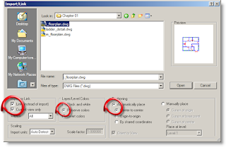
Link instead of import because you never know when the dwg might change, and it doesn't take up as much memory as does straight importing. It should be pointed out that even though linking a dwg is better than importing, you should always be aware that the more dwg's imported into the project the slower it will run. To avoid this you should delete files no longer necessary to the project. Current view only to take advantage of the option on the option bar allowing you to toggle between foreground and background. Preserve colors so you will be able to tell the difference between your model and the dwg lines. Automatically place Center-to-center Revit will search for the center of the dwg and place it into the center of your Revit project. It is possible to acquire the coordinates of the dwg. Typically the civil engineer will use these coordinates to begin their drawing in AutoCAD. We will discuss how to do this in an upcoming post.
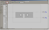
Adding Walls Start by making sure the settings for your wall are correct. Do this by checking the Options Bar at the top of the View Window. After choosing the wall, you'll need to decide how you want to go about building your walls. On the Options Bar you can choose to either pick the lines in the DWG or draw the lines over the top of the DWG. Either way you must pay close attention to how the wall is being drawn. When you begin to draw you'll get a green dashed line showing where the Location Line is. This should help you determine how the wall is going to look once created. This video tutorial should help: Click here if you're on the SmithGroup network. Click here if you're not on the network.

Welcome to revitED!

RevitED (Revit Education) and general BIM topics. I've been using Revit now for 11 years, and though I feel I've got a pretty good handle on the software it seems each day I learn something new. I want to share that with the readers of this blog and hope you learn something new as well.