Area Plans are views that show spatial relationships based on area schemes and levels in your model. You can have multiple area plans for every area scheme and level. Each area plan can have distinct area boundaries, tags, and color schemes.
The question is when to use the area plan in the first place. Well, let’s say you want to color up a plan to show a client the different departments the building has. Or maybe you need to count up the square footage or a specific portion of the building. Or you need to create a life safety plan that shows different areas within a specific department. The easiest way to accomplish this is to use Area Plans.
Once you’ve got a floor plan set up you can create an Area Plan from it. The first thing you should do is set up a Color Fill Scheme. Select Settings → Color Fill Schemes, this opens the Edit Color Scheme dialog. Here you’ll be able to create new schemes and customize them to suit your needs. Click here to learn more about how to create Color Schemes. Once you’ve created the color scheme return to the plan view you want to create an Area Plan from and click the Room and Area tab on the Design Bar.
Note: If you do not see the Room and Area tab on the Design Bar, right click in an empty space in the Design Bar and select it from the list.  After clicking Area Plan select the level for the plan you want to create and then click OK. You will be asked you if you want Revit to create area boundary lines associated with the exterior walls automatically. This is up to you. If you choose no you’ll have to draw them in yourself. If you choose yes the boundary lines on the exterior walls will be drawn automatically, but you will have to draw in all other boundary lines. Before you start creating all the boundary lines, open the View Properties and choose the Color Scheme you created from the Color Scheme parameter in the instance parameters. Next, draw in all the boundary lines to create areas in the plan. Select the Area tool and place it one by one over the area
 s you created in the previous steps. This is similar to creating rooms with the room tool. As the areas are being placed they will be colored with respect to the color fill scheme you created and added to this view. The last thing to do is add the Color Scheme Legend. You do this by clicking the Color Scheme Legend tool and then with your cursor placing it in the view in an appropriate location.
Remember the Area Plan tool is an effective way to graphically show specific areas as well as creating life safety plans.
s you created in the previous steps. This is similar to creating rooms with the room tool. As the areas are being placed they will be colored with respect to the color fill scheme you created and added to this view. The last thing to do is add the Color Scheme Legend. You do this by clicking the Color Scheme Legend tool and then with your cursor placing it in the view in an appropriate location.
Remember the Area Plan tool is an effective way to graphically show specific areas as well as creating life safety plans.
I don't know about you but I hate it when I try to orbit in a 3D view and for some reason the entire model goes missing. Well this is because when you begin a project and start modeling, you establish an origin. Then when you're in a 3D view and you try to orbit, Revit wants to orbit the view around the original origin. The way to override this is to select a part of the model and then orbit. When you select a part of the model you temporarily make it the new origin thus telling Revit to orbit around it.
Well, the title may be little dramatic, but the reason I haven't posted in a while is because of the stairs tool. I spent the last four days trying to fix a stair problem that could have been avoided.
If you've ever used the stair tool you know how frustrating it can be. I hope with this post I can shed some light on the stairs tool and cut some frustration out of your life.
 First of all, as with anything in Revit, creating stairs requires some forethought. This is especially true if you're creating a multistory stair. You will most definitely want to create the first level stair as a single stair. Don't include it as part of the multistory stair. The reason is because the first level stair probably has some unique conditions. The included image might be one of those unique conditions. I still suggest creating a multistory stair on the stairs that will absolutely be the same from beginning to end. Now don't get ahead of yourself. You typically don't want to include the last stair as part of the multistory stair either for the same reasons you wouldn't include the first stair. The last stair is probabl
 y going to be different. Now if you haven't guess by now the reason you don't want to make the entire staircase one single multistory stair is because if you make a change to any part of said stair it will change it on all levels. This will result in much swearing and I don't want to get blamed for it SO DON'T DO IT. This topic will be a Revit Lunch and Learn Series, so there is more to come later. Meanwhile give it try.
Click here for video tutorial on how to create stairs.
y going to be different. Now if you haven't guess by now the reason you don't want to make the entire staircase one single multistory stair is because if you make a change to any part of said stair it will change it on all levels. This will result in much swearing and I don't want to get blamed for it SO DON'T DO IT. This topic will be a Revit Lunch and Learn Series, so there is more to come later. Meanwhile give it try.
Click here for video tutorial on how to create stairs.
As many of you know walls consist of several layers. These layers make up the total width of the wall assembly. The layers are made up of different materials assembled by you or whoever has constructed the walls you use. Often times we need to extend a portion of these walls without extending the entire wall. Luckily Revit allows you to do this. Here’s how:
Select the wall you wish to change. Right click and choose the Element Properties or simply select the Element Properties button on the Options Bar. Click the Edit/New button to open the Type Parameters. Then click the Edit button for the Structure parameter. This takes you to the Edit Assemblies dialog. Make sure you click the preview button located at the bottom left hand corner of the dialog. The preview shows you a plan or section view of the wall. Below th e preview window click the view drop down window and choose Section: Modify Type from the list. In the Modify Vertical Structure (Section Preview Only) area located at the bottom of the dialog, select Modify. In the preview window zoom in on the top of the wall, and select the top Outer Boundary of the layer in which you want to move. Once selected a padlock will appear, click to unlock it. This will allow you to move that particular layer independently of all the others. Note: To achieve the desired look you must unlock all the layers you want to move. In this case I unlocked all the layers except the CMU to represent a furring wall that doesn’t extend all the way up. Your wall may be different. You may need to unlock the layers from the bottom for example. When you have unlocked all the layers needed to achieve the desired look click OK three times to exit the Element Properties dialog box to return to the project. Now when you select the wall in an elevation or 3D view you will notice an ex
 tra Shape Handle (grip). This represents the layer or layers you unlocked in the Edit Assembly dialog. You can now pull it up or down independent of the other layers in the wall. Also if you go into the Element Properties under the Instance Parameters you’ll notice a parameter that was previously un-editable, (Top Extension Distance), is now editable. You can change the height of the unlocked layers from here as well. Go ahead, give it a try.
Creating Revit materials may sound a bit intimidating, but honestly it’s pretty straight forward. This post will cover how to create and use new materials in Revit Architecture 2009.
To create a material, first find an existing material that is as close as possible to the new material. For example, the existing material should have the same material class as the new material. It should also have many properties that are the same as or similar to the new material. This strategy reduces the amount of work you must perform to define the new material. It also increases the likelihood that the new material will perform as expected in the building model.
 Click Settings → Materials to access the Materials dialog. At the bottom of the left pane of the Materials dialog, click Duplicate. Or you can right-click a material in the list, and click Duplicate.
In the Duplicate Revit Material dialog, for Name, enter a name for the new material, and click OK.
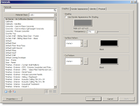
On the Graphics tab of the Materials dialog, specify display properties for the new material, and click Apply. To change how the material looks in shaded views (such as 3D views and elevations), under Shading, do the following:
If you want to use the render appearance to represent the material in shaded views, select Use Render Appearance for Shading. Revit Architecture calculates an average color for the render appearance and uses it to represent the material in 2D and 3D views whose model graphics style is Shading or Shading with Edges. Click the color swatch. In the Color dialog, select a color. Click OK.
For Transparency, enter a value between 0% (completely opaque) and 100% (completely transparent), or move the slider to the desired setting. To change how the outer surface of the material displays in views (such as plan views and section views), under Surface Pattern, do the following:
To change the Surface Pattern, click the arrow, and select a pattern from the list. To change the color that is used to draw the surface pattern, click the color swatch. In the Color dialog, select a color. Click OK.
To change how the cut surface of the material displays in views, under Cut Pattern, do the following:
To change the cut pattern, click the arrow, and select a pattern from the list. To change the color that is used to draw the cut pattern, click the color swatch. In the Color dialog, select a color. Click OK. Click Apply.
On the Render Appearance tab of the Materials dialog, specify a render appearance for the new material, and click Apply.
Do the following:
If you want to...
change the preview of the render appearance
Then...
For Scene, select the desired scene from the list. Click Update Preview. The preview is a rendered image of the material. Updating the preview takes a moment while Revit Architecture renders the preview scene.
If you want to...
select a different render appearance
Then...
Click Replace. Select a render appearance. Click OK.
If you want to...
align the texture of the render appearance to the surface pattern of the material
Then...
Use the Texture Alignment tool to align the texture of the render appearance to the surface pattern of the material (defined on the Graphics tab of the Materials dialog). When you render a 3D view, the rendered image displays the texture, positioned as specified using the Texture Alignment tool.
If you want to...
change properties of the render appearance
Then...
In the lower part of the Render Appearance tab, change property values. The properties vary depending on the type of render appearance.
Note: The render appearance can affect the amount of time required to render an image.
If you want to...
update the preview to reflect changes
Then...
Click Update Preview. The preview is a rendered image of the material. Updating the preview takes a moment while Revit Architecture renders the preview scene.
Click Apply.
On the Identity tab of the Materials dialog, enter information about the new material, and click Apply.
(Optional) On the Physical tab of the Materials dialog, specify physical parameters for the new material, and click Apply.
To exit the Materials dialog, click OK.
Click Settings → Materials to access the Materials dialog. At the bottom of the left pane of the Materials dialog, click Duplicate. Or you can right-click a material in the list, and click Duplicate.
In the Duplicate Revit Material dialog, for Name, enter a name for the new material, and click OK.
On the Graphics tab of the Materials dialog, specify display properties for the new material, and click Apply. To change how the material looks in shaded views (such as 3D views and elevations), under Shading, do the following:
If you want to use the render appearance to represent the material in shaded views, select Use Render Appearance for Shading. Revit Architecture calculates an average color for the render appearance and uses it to represent the material in 2D and 3D views whose model graphics style is Shading or Shading with Edges. Click the color swatch. In the Color dialog, select a color. Click OK.
For Transparency, enter a value between 0% (completely opaque) and 100% (completely transparent), or move the slider to the desired setting. To change how the outer surface of the material displays in views (such as plan views and section views), under Surface Pattern, do the following:
To change the Surface Pattern, click the arrow, and select a pattern from the list. To change the color that is used to draw the surface pattern, click the color swatch. In the Color dialog, select a color. Click OK.
To change how the cut surface of the material displays in views, under Cut Pattern, do the following:
To change the cut pattern, click the arrow, and select a pattern from the list. To change the color that is used to draw the cut pattern, click the color swatch. In the Color dialog, select a color. Click OK. Click Apply.
On the Render Appearance tab of the Materials dialog, specify a render appearance for the new material, and click Apply.
Do the following:
If you want to...
change the preview of the render appearance
Then...
For Scene, select the desired scene from the list. Click Update Preview. The preview is a rendered image of the material. Updating the preview takes a moment while Revit Architecture renders the preview scene.
If you want to...
select a different render appearance
Then...
Click Replace. Select a render appearance. Click OK.
If you want to...
align the texture of the render appearance to the surface pattern of the material
Then...
Use the Texture Alignment tool to align the texture of the render appearance to the surface pattern of the material (defined on the Graphics tab of the Materials dialog). When you render a 3D view, the rendered image displays the texture, positioned as specified using the Texture Alignment tool.
If you want to...
change properties of the render appearance
Then...
In the lower part of the Render Appearance tab, change property values. The properties vary depending on the type of render appearance.
Note: The render appearance can affect the amount of time required to render an image.
If you want to...
update the preview to reflect changes
Then...
Click Update Preview. The preview is a rendered image of the material. Updating the preview takes a moment while Revit Architecture renders the preview scene.
Click Apply.
On the Identity tab of the Materials dialog, enter information about the new material, and click Apply.
(Optional) On the Physical tab of the Materials dialog, specify physical parameters for the new material, and click Apply.
To exit the Materials dialog, click OK.
Welcome to revitED!
RevitED (Revit Education) and general BIM topics. I've been using Revit now for 11 years, and though I feel I've got a pretty good handle on the software it seems each day I learn something new. I want to share that with the readers of this blog and hope you learn something new as well.
 After clicking Area Plan select the level for the plan you want to create and then click OK. You will be asked you if you want Revit to create area boundary lines associated with the exterior walls automatically. This is up to you. If you choose no you’ll have to draw them in yourself. If you choose yes the boundary lines on the exterior walls will be drawn automatically, but you will have to draw in all other boundary lines. Before you start creating all the boundary lines, open the View Properties and choose the Color Scheme you created from the Color Scheme parameter in the instance parameters. Next, draw in all the boundary lines to create areas in the plan. Select the Area tool and place it one by one over the area
 s you created in the previous steps. This is similar to creating rooms with the room tool. As the areas are being placed they will be colored with respect to the color fill scheme you created and added to this view. The last thing to do is add the Color Scheme Legend. You do this by clicking the Color Scheme Legend tool and then with your cursor placing it in the view in an appropriate location.
Remember the Area Plan tool is an effective way to graphically show specific areas as well as creating life safety plans.
s you created in the previous steps. This is similar to creating rooms with the room tool. As the areas are being placed they will be colored with respect to the color fill scheme you created and added to this view. The last thing to do is add the Color Scheme Legend. You do this by clicking the Color Scheme Legend tool and then with your cursor placing it in the view in an appropriate location.
Remember the Area Plan tool is an effective way to graphically show specific areas as well as creating life safety plans.


