Thursday, May 11, 2017

What is FormIt and Why Do I Care?

There's no question we use a lot of tools in the design process. In addition to Reivit we use, Sketchup, Rhino, Navisworks, Enscape, C3D, and Dynamo, just to name a few. So this post is about yet another tool to go in your tool belt. But stay with me. I'm going to explain why you should be interested in using FormIt.

What is it?

FormIt is an Autodesk product that looks and feels a lot like Sketchup. Some of the modeling techniques are similar and it's really fluid like Sketchup. So you may be asking yourself... "If I have Sketchup, why do I need Formit?" Keep reading.

Conceptual Model with Revit

  • Conceptual mass families created in FormIt become Revit mass families
  • Lefel created in FormIt become levels in Revit
  • FormIt models with materials appplied

Conceptual Modeling with Revit Content in FormIt

  • Groups in FormIt can be categoriezed to become Revit families
  • Revit families can be exported as FormIt groups and then converted back into the original Revit family.

Why Do I Care?

Ask yourself one question. Do I car about becoming more efficient at what I do? If the answer is yes and you find yourself struggling with the Sketchup to Revit workflow, give FormIt a try. FormIt has a short learning curve that can be overcome in just a few days. 
Oh, I almost forgot. FormIt can be launced from the Chorme web browser and is also available on mobile devices. The FormIt team has always wanted you to be able to design anytime anywhere.
Of course FormIt isn't perfect. It's a fairly new product and is still maturing. However, if you want to explore the possibilities of becoming more efficient by using a tool more compatible with Revit, give FormIt a try. What do you have to lose?

Click here to learn more about designing in 3D anywhere and here to learn more about designing with intelligence. 


Monday, March 20, 2017

Visibility Checklist - 10 Ways to Find What You're Missing in Revit Views

No question about it, the number one reason people call me is to help them find something that’s gone missing in the view they’re working in. So I thought it would be helpful to create a checklist of where I look when something has gone missing.


Visibility Graphics Dialogue

This is the first place I start. Check to make sure the category of the element you're missing is on in the VG dialogue.
If the category is on, make sure the sub-category is on. This is often overlooked so be sure to expand the category to expose the sub-categories.
Sometimes, however it’s a nested family category that you have to watch out for. In the example below you’ll notice the door category and sub-categories are on in the VG dialogue. However there is part of the door family that is not displayed. That’s because the door contains a nested family from the Detail Item category. This is also true for any linked model. Each linked model has its own set of VG, so make sure you check them.


Worksets

Check to make sure all the worksets are visible. Even if set to visible or show, elements on a Closed workset will not be visible.

Make sure all the worksets are open. If any are closed you can open them in the Workset dialogue from the Manage Collaboration panel on the Collaboration tab on the ribbon.

Filters

To ensure a filter is not the culprit, make sure they're all visible. If a filter is the cause of the visibility issue you may have to edit it to avoid showing items that have been intentionally hidden with the filter. Check with your team members before editing or removing filters.


Design Options
Check the Design Options tab in the VG dialogue. The element you're looking for may be on a different DO than what's set in the view. You can temporarily change this setting to show any of the DO. Note: DO only work with 3D elements. 

View Range

Check to make sure the element you're looking for falls within the Primary View Range. If it's outside this range you won't be able to see it. If the element does fall outside the primary range, you may not want to change it right away. Discuss this with your team to make sure you're not affecting someone else's setting. 

Plan Region

Plan Regions control a separate view range in floor plan views. Check the VG dialogue for Plan Region visibility in the view. If Plan Regions are visible, check their view range settings. 

Hide at Scales Courser Than

If you're missing a callout, section, or elevation marker be sure to check the view properties setting "Hide at scales courser than" in the missing view. The scale of the view may be the reason why any one of these view markers are not showing up.

Detail Level

Any loadable family can have it's visibility set to Course, Medium, or Fine. If the visibility of the element is set to something other than what you have your view set to, it will not show up. This setting will also effect nested families so you may have to edit the family to get to the bottom of it.


Manually Hidden Elements

Don't forget to simply check for hidden elements by clicking the Reveal Hidden Elements button on the view control bar.


Phases

If your project has phases there's a good chance your missing element was created on the wrong phase and the phase filter in the view is causing the issue. Make sure to check both the view as well as the element phase settings. 


Ideate Revit Add-in to the Rescue!

X-Ray is an add-in tool the will help you find what you're missing. In addition to helping you find missing stuff it will explain why it's missing, which is always a good thing. 

When things go missing in Revit it's easy to blow your top. Just slow down and work through these 10 areas and you're sure to find what you're missing.


Sunday, December 11, 2016

Check out my new Revit MEP course on Pluralsight!

Hey everyone. Hope you're having a great holiday season. I just wanted to put in a shameless plug for my new course on Pluralsight
This course is geared toward those who have never opened Revit MEP. I'm really proud of this course and believe it's just what people are looking for. If you or someone you know are looking for a truly fundamentals course with some excellent commentary, then please, check out my course.  

Tuesday, September 6, 2016

I know I put that CAD file in here somewhere

I know it's hard to believe, but we still use CAD files, shocking isn't it? Even though civil, landscape, and other consultants participate in the BIM process, they don't always work in Revit, therefore sometimes we link in dwg's from them. And that's OK. We're still in a transition stage in the industry and may be in this stage for a little while longer. In the meantime there are some nuances when it comes to linking and viewing dwg's in Revit.


Nested vs Direct Link

Of course you know you should always link dwg's instead of importing, but maybe you didn't know it's possible to view nested dwg's. Let me explain. If the architect links a dwg provided by civil, landscape, or even a furniture vendor into the architecture model, and then the architecture model is linked into a different Revit model, you have a nested dwg. Whomever the beneficiary of this linked model now has the ability to view the nested dwg without having to directly link the dwg into their model. Please be aware that if the architect links the dwg to the "Current View Only" option, the "Linked View" in the RVT Link Display Settings dialog will have to be set to that specific view.


The downside to Nested Links

The downside to nested links is you can't control the dwg layers as easily as a direct link. Direct linked dwg's allow you to query the object and either hide or delete layers from the Import Instance Query dialog. In a nested dwg scenario you can still control the layers, but you have to do it through the RVT Link Display Settings> Import Categories tab. In this scenario you can't query the lines so it helps to know the layers that make up the line work in the dwg. 
 In the end either method works. There are advantages and disadvantages to both. The next time you have to link a dwg into your model, decide as a team how you approach it. This potentially affects all team members regardless of discipline. Discussing this up front on a team level will yield a more consistent work flow which improves your process. 


Monday, August 1, 2016

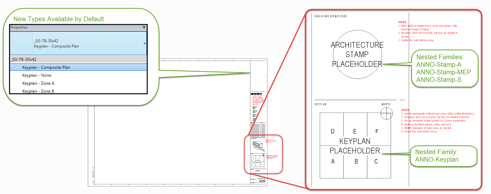
Nested Key Plan and Stamp families... Am I late to the party?

Why didn't I think of this sooner? 

Actually why didn't I think of this at all? We just implemented nested stamp and key plan families in our title block families. I wish I could say it was my idea, but as is usually the case one of our power users suggested it.

I love things that make our lives easier

All we did is create place holder annotation families  for a stamp and a key plan. Then we nested those place holder families into our standard title block. Now when people want to add a stamp or key plan all they have to do is edit the nested family, reload it back into the title block, then load the title block into their project. All the visibility parameters are already assigned so people don't have to worry about if they're that step. Because let's face it. People forget that step, and if you forget that step you get nothing when you flick the visibility switch.

It's the little things. Actually this one is huge!
 

Friday, July 8, 2016

Callouts Confusion

Choose wisely 

I've come across this a hundred times. People ask me why they can't see their elevations in callout views. Well the reason you can't see them is because elevations are not allowed in a detail view. If you're not paying attention you may inadvertently choose a detail view when placing a callout in floor plan. If you want to see your elevations in the callout make sure you choose a floor plan callout type. It's the little things.   


Wednesday, June 22, 2016

Profiling Curtain Wall Mullions


What Revit categorizes as curtain wall we use for anything from actual curtain to skin, store front, interior partitions, windows and so much more. It's a very versatile tool. And as versatile as the curtain wall is the mullions we place in them are less so, or so it would seem. 


Revit works like this...

Each mullion type is based on a profile family. The profiles that ship with Revit are system profiles. You'll notice in the type properties of the mullions, the profile is set to either Default or in some cases System Mullion Profile: Rectangular. Corner mullion families don't reference a profile at all. You cannot edit these profiles and there are only a few parameters to adjust them. You can change the profile in the type properties of all mullion types except the corner mullions

(Warning! Corner mullions are not easily reloaded into a project. Take care when purging models to avoid purging corner mullions)

Don't like it? Customize it

The good news is you don't have to settle for the out of the box mullions. There is a Revit family template specifically designed for the creation of mullions. Since mullions are base on profiles, the skies the limit as to the shape you want to create... almost. There are limitations of course, but there's one mullion profile I want to focus on in particular. The mullion used with a butt glazed joint is a popular one and I'm asked all the time how to create it. It's actually not too difficult, but there are definitely some tips and tricks that you have to know to make this one work the way it should.


Read the fine print!

As stated earlier, mullions are just profile lines drawn two dimensionally. Revit does the rest for you. Don't forget to read the little note in the mullion profile family template about where curtain panels are trimmed what a mullion is inserted into the curtain wall. Understanding this makes all the difference. I like to add a dimension parameter to the length of the mullion so it's easy to stretch. You can also add a width dimension parameter to it for even more control. 

Load it up

Load this family into your project and add it to a mullion family. You can either duplicate one of the existing mullion families or right click on the family and choose create new type. Then just switch out the mullion profile in the type properties with the new one you created. 


A few minor adjustments 

Making adjustments to this family isn't exactly straight forward. For example, to adjust it you have to edit the type properties in the mullion family as well as the profile family.

Revit is a Calculator!

I find few people know this little tidbit. Adding an equal sign in front of an expression turns Revit into a calculator. You can use this little trick almost anywhere you have a dimension. That means you don't have to guess what 4.5" + 1 21/64" to adjust the length of this mullion. You can let Revit do the math for you. 
It's 5 53/64" by the way. 


Here's the final curtain wall with butt glazed panels. I hope this was helpful and adds to your work flow. Certainly if you have any questions about how to create your own mullion profile please do not hesitate to ask me. 
Also I'd like to hear from you if you have any other uses for the Revit Calculator. I'd be interested in hearing about any use cases where you found it useful. 

Profiling Curtain Wall Mullions


What Revit categorizes as curtain wall we use for anything from actual curtain to skin, store front, interior partitions, windows and so much more. It's a very versatile tool. And as versatile as the curtain wall is the mullions we place in them are less so, or so it would seem. 


Revit works like this...

Each mullion type is based on a profile family. The profiles that ship with Revit are system profiles. You'll notice in the type properties of the mullions, the profile is set to either Default or in some cases System Mullion Profile: Rectangular. Corner mullion families don't reference a profile at all. You cannot edit these profiles and there are only a few parameters to adjust them. You can change the profile in the type properties of all mullion types except the corner mullions

(Warning! Corner mullions are not easily reloaded into a project. Take care when purging models to avoid purging corner mullions)

Don't like it? Customize it

The good news is you don't have to settle for the out of the box mullions. There is a Revit family template specifically designed for the creation of mullions. Since mullions are base on profiles, the skies the limit as to the shape you want to create... almost. There are limitations of course, but there's one mullion profile I want to focus on in particular. The mullion used with a butt glazed joint is a popular one and I'm asked all the time how to create it. It's actually not too difficult, but there are definitely some tips and tricks that you have to know to make this one work the way it should.


Read the fine print!

As stated earlier, mullions are just profile lines drawn two dimensionally. Revit does the rest for you. Don't forget to read the little note in the mullion profile family template about where curtain panels are trimmed what a mullion is inserted into the curtain wall. Understanding this makes all the difference. I like to add a dimension parameter to the length of the mullion so it's easy to stretch. You can also add a width dimension parameter to it for even more control. 

Load it up

Load this family into your project and add it to a mullion family. You can either duplicate one of the existing mullion families or right click on the family and choose create new type. Then just switch out the mullion profile in the type properties with the new one you created. 


A few minor adjustments 

Making adjustments to this family isn't exactly straight forward. For example, to adjust it you have to edit the type properties in the mullion family as well as the profile family.

Revit is a Calculator!

I find few people know this little tidbit. Adding an equal sign in front of an expression turns Revit into a calculator. You can use this little trick almost anywhere you have a dimension. That means you don't have to guess what 4.5" + 1 21/64" to adjust the length of this mullion. You can let Revit do the math for you. 
It's 5 53/64" by the way. 


Here's the final curtain wall with butt glazed panels. I hope this was helpful and adds to your work flow. Certainly if you have any questions about how to create your own mullion profile please do not hesitate to ask me. 
Also I'd like to hear from you if you have any other uses for the Revit Calculator. I'd be interested in hearing about any use cases where you found it useful. 

Tuesday, June 14, 2016

A Tale of Two Ceilings

Have you ever wondered why there are two ways to create a ceiling? It seems like the obvious choice between sketching a ceiling and allowing Revit to automatically create one would be the latter... wouldn't it? Of course for the automatic ceiling to work you have to have bounding elements, therefore in situations where you don't have these elements, i.e. walls, you're going to have to sketch it. For clearly defined spaces where there are walls defining the space, using the automatic ceiling seems like the obvious choice.

Automatic or Sketch

When you create a ceiling, Revit wants to host the boundary of that ceiling to the walls that define the space. It does not matter which method you choose to create the ceiling, Revit will host the boundary of the ceiling to the walls. The difference is when you SKETCH a ceiling in a space with unjoined collinear walls, Revit chooses one to host to leaving the other one free to move. Now you may be thinking this isn't a big deal, but keep reading the payoff is coming.   


Here's the rub

In the design process you may use generic wall types to define a space until you know which wall type you're going to use. Some may have different materials which can result in walls having different thicknesses. Because of this these walls don't always "join" together to make one continuous wall, and they don't always align perfectly. There are two things that occur that will cause this warning. Changing the wall type such that the thickness of the wall changes causing the face to break the collinear alignment with the adjacent wall, and moving one of the walls which also causes the faces of the walls to become misaligned. 


 Save the Ceilings!

Deleting the ceilings could affect the model of anyone who has the architects model linked. Our esteemed engineers host elements to the architecture ceilings all the time, therefore deleting them would leave any hosted elements orphaned. We don't want that. 

If you're not sure which ceilings are affected you can expand the tree in the warning dialog and all the affected elements are listed there. Checking the box and clicking the "Show" button will take you right to the ceiling.


Once you know which ceilings are affected you can fix them. Select the ceiling and choose the Edit Boundary button on the ribbon. It's not a difficult fix, but if you have a lot of ceilings to fix it could get tedious.


I'm a big fan of the automatic ceilings method. It's a fast and efficient way to place ceilings. IMO if you're careful and attentive to the spaces in which you're placing ceilings the automatic method is still the way to go. Having said that, if you feel sketching the ceilings and not having to worry about them failing if you change a wall in some way saves you time, then that should be the method you use.  

Thursday, July 11, 2013

Revit across the internet?

Great post today from Steve over at OpEd. He brings up a good point about trying to make Revit do things it's not really designed to do. Often time these work arounds end up costing you more time and money in the long run. I had similar issue this morning. My firm is currently working with another firm on a project located in a different state but close to one of our offices. The local firm is the prime and we're handling the interiors. At the beginning of the project it was decided that everyone work in the same model and we'd use Revit Server to host the models. If you used Revit Server before you know that working over different networks is very difficult and not really supported by Autodesk anyway. However, we do it because we are gluttons for punishment and because we want the ability to work in the same model. 

This method worked while the model was small and few people were working in it. Once the model grew and more more links were added it became apparent hosting the model in a single location and creating local files over VPN access was the wrong decision. At the worst point it was taking 4.5 hours to open the model. This was not sustainable and of course it disrupted the work flow of all those involved in the project. We then had to brainstorm to figure out the best way to resolve the problem. We settled on creating dead links for the MEP model as well as the structural model which has it's own set of problems. The project is now running somewhat smoothly with 30min. sync times. If it gets worse we're thinking of sending our staff to work from our partners office until the project is done. 

I guess the moral of the story is two fold. Planning is everything and if at all possible don't try to make Revit do what it's not really designed to do.    

Wednesday, October 5, 2011

Design Review Mobile

So I just wanted to post a little something about the new Design Review Mobile and Autodesk Cloud services. I've been able to test this new service from Autodesk using one of the ipads in our office. In my opinion this will at some point become a usable service, but right now...not so much. I was able to download the app and get up and running easy enough. Uploading files to the cloud was a piece of cake. The markup tools are simple and easy to use, and because you're working on the cloud those mark ups are automatically visible from the viewer on the cloud.
I had a bit of trouble manipulating the 3D model. It's a bit difficult to spin the model around to the opposite side if you need to see that. In fact I haven't been able to get around to the back side of my model using my ipad yet. Pan and zoom work great, orbiting is a bit tricky especially when you can't establish a pivot point.
In addition to the 3D model viewing trouble I, and a few others, had problems with viewing 2D dwf sheet views generated from Revit. We all had the same problem. When trying to view the sheet view we'd get an error saying "The page you are attempting to view is too large to be displayed on your device.", which didn't make much sense since the 2D views were much smaller than the 3D view.
This was the explanation from Autodesk:
"This error means your device's available memory isn't large enough to hold the data contained in a given sheet. There are many factors which contribute to this size, including the number of and size of embedded bitmaps and the number of total drawable objects in a sheet.

This error does not mean that the sheet's resolution is too large, that there isn't enough storage space on your device, or the original document's file size is too large. It has no relation to your Autodesk Cloud Document storage capacity.

 
We are investigating what options there are for supporting larger 2D data sets on these low memory devices. However, currently if you encounter this error on your device it means the sheet takes up too much memory on the device to be viewed."
 
Still waiting to hear from them on what options there are for supporting large 2D data sets. All in all I'm pleased to see this type of move from Autodesk. I think once we're able to work out the kinks this will be a great way for CA folks to work in the field. No more lugging around a huge set of drawings, quicker response times for errors and problems in the field.
 
So if you've got an ipad download the app and give it a whirl.

Tuesday, October 4, 2011

I'm back!

So I understand this is the first post I've done in a while, but I've turned a new leaf what can I say.

While reading a post from David Light's blog this morning he referenced an article written by Martyn Day for AEC Magazine. Below is a quote from the article. I'm amazed at how software is driving the hardware these days.


"The single model utopia also does not make sense from a hardware perspective. Depending on the software being used, BIM models get very big, very fast. David Light from HOK recently told me that the firm is stipulating 24GB of RAM for its new workstations so it can hold the Revit datasets without paging to disk on its biggest projects. This is a considerable investment. BIM simply cannot run on old machines designed for running AutoCAD or VectorWorks. Other BIM modellers are not quite so memory hungry but they still quickly start to swell as the model detail grows."

Great article...give it a read.


Monday, August 3, 2009

Worksharing

I've often find that instructing students on how to set up worksets is particularly difficult. The concept is so different from anything else they've done it seems to pass about ten feet above their heads. I must admit, when I first heard the term worksharing I didn't understand it either. So now after five years of Revit use I think I have it down. I'll try to explain it as simply as I can. A project doesn't just start out with Worksharing, one has to enable it. To do so open up a new file and select the Worksharing tool on the toolbar. If you don't see this tool, right click the toolbar area and select Worksets from the list. Next, click the Worksharing Icon to the left of the Active Worksets window. This will bring up the Worksharing dialog box. In the dialog box you'll see two boxes, one labeled Shared Levels and Grids, the other Workset 1. Leave the titles as they are and click OK. Once you've clicked ok there's no turning back. The now when elements are placed or coppied they well be assigned to a workset. You must pay very close attention to the active workset. While this workset is active everything is place on it automatically. I cannot stress this enough. It is, however, possible to select elements and change the workset they belong to, but it's much easier to place them on the correct worksets the first time. DO NOT TREAT WORKSETS LIKE AUTOCAD LAYERS. I've seen this happen time and time again. Worksets are use to break a project up so it is more managable. Worksets are not to be used solely for the purpose of visibility settings. This is what Visibility Graphics and Object Styles are for. For example, an obvious strategy to separate a project is by buildings. If a project has more than one building, then it's easy to separate them out and place them on separate worksets. Maybe it's by core and shell, and the interior of the building. Find a logical breaking point in the building to separate it out. Consult you BIM manager if you have one. That's it, as simple as 1 2 3...right?

Thursday, July 9, 2009

WU1 now available for download

Finally, WU1 is here. After all the negative things I heard about 2010 crashing, I wasn't about to use it on a project. So I've been waiting patiently for the WU. Thanks Autodesk for getting that out quickly...(eyes rolling). Anyway follow the link to the Revit Architecture or Revit MEP update enhancement list. Some pretty good stuff. It looks like Autodesk is hard at work trying to fix stuff.

Monday, July 6, 2009

Exporting to CAD

For the most part exporting is as easy as 1-2-3. However there are a few things you should be aware of before exporting. First of all you should make sure the Export Layers txt file is in order. Meaning if you haven't created one for you office, now's the time. It's not too difficult really, all you have to do is follow some basic rules. Revit uses a txt file to map categories and subcategories from Revit to layer names and color numbers in Acad. The format is as follows: Category (tab) Subcategory (tab) Layer name (tab) Color number (tab) Cut Layer name (tab) Cut color number. If there isn't a subcategory then you simply skip it. This is an image of the AIA export layers txt file that comes with Revit. You can always use this one to get started and just save as to create one specific to your office standards. Once you've created the txt file, all you have to do is map the file location in the import/export settings. You do this by clicking the file drop down menu and selecting Import/Export Layers Settings. From there choose the format; DWG/DXF, DGN... Once you choose you can load the txt file into your project and you'll be able to see the Category and Layer name along with the cooresponding Color ID Number. The cool thing about this txt file is you can save it on your network somewhere and path it to your Revit template so you'll never have to do this again.

Thursday, May 14, 2009

ACE Seminar

So I'm sitting here in the Fiesta Inn, in Tempe listening to all these presentations about BIM. For the most part the discussions have been centered around the contractor or the sub-contractor. One subject in particular as hit home with me. How do you share the BIM model? To me it depends largely on how the project is contracted. If you're talking about a CM at risk contract then responsibility for sharing the BIM model becomes a little gray. The architect may not want to share the model with the contractor because they may feel they're doing part of the contractors job. Even if the architect does share the model, the contractor may not want it because it wasn't modeled to a contractors specifications. In other words the contractor is going to want to extract information from the model that the architect may not have modeled. For example, the architect may not model the footings or foundation walls. He or she may decide it's not worth modeling and just pick up that information in a detail view. This will not be acceptable for the contractor. The contractor can't use the information that isn't there. If however the contract is written as a design build, where the contractor is driving the boat, they can dictate to the architect how the model should be built. They can do this because in this case the architect is under contract with the contractor. I'm not sure what the solution is, but knowing these discussions are taking place makes me hopeful for the future.

Monday, February 23, 2009

Corner Mullion

Ever want or need to create a new corner mullion for Revit only to realize you can't do it. Corner mullions are system families, so you have the ability to change the look to the ones already in Revit, but you can't create a new family. So as I was reading the AUGI forums the other day I came across a post that talked about adding corner mullion to a curtain panel family. So I tried it and the results speak for themselves. It's not a difficult build, but not for the casual user either. I create the corner mullion as a nested family so I could control the size and placement of the mullion.

Tuesday, January 27, 2009

Plotting Concerns?

It's true, when plotting from Revit there is reason to be concerned, with the settings that is. For the most part the settings are fairly straight forward, but you should be aware of a couple that might surprise you. Make sure when plotting you know what you're plotting. In Revit you have 3 choices when it comes to the Print Range. Current Window will consider everything in the View Window regardless if you can see it or not. This means if you've set it to center the plot, you may get some weird results since Revit is trying to center everything in that view. Visible portion of current window will allow you to have other elements in the view window but the plot will be only what you see. You should understand that the plotter will try to place a border on the sheet, so you may have to zoom out a bit to get everything you want to see. Lastly, Selected views and sheets is an excellent way to plot many sheets or views from the same plot dialog. You have to be careful when using this because once you choose to use it, Revit remembers the last selection, so make sure you check none first and then select the views and/or sheets you wish to plot. If you forget, you may end up with more plots than you want. Remember this is NOT a batch plot. When plotting many sheets or views you have to wait until the plot data has been transferred to the plotter. Depending on how many sheets or views you've sent will determine how long you have to wait before being able to resume your work. If you're on subscription you'll be able to avoid this by downloading the Batch Plot utility from Autodesk. The last comment I have on plotting is, once you've set up your settings you can save them. This will allow you to choose it when you plot instead of having to reset everything every time.

Welcome to revitED!

RevitED (Revit Education) and general BIM topics. I've been using Revit now for 11 years, and though I feel I've got a pretty good handle on the software it seems each day I learn something new. I want to share that with the readers of this blog and hope you learn something new as well.